|
|
|
Categories
|
|
Information
|
|
Featured Product
|
|
|
 |
|
|
There are currently no product reviews.
 ;
A very easy to understand and use manual. Well worth the money.
 ;
Very good information with clear drawings. Thanks!
;
The ease of this purchase was a good start. The content of this manual was exactly all I needed to retore my Tandberg 64.
All of the mechanical and electrical information is contained in the manual and the quality of the document makes reading the data easy.
The exerience with the resource has made this my prime source for technical data.
;
Owner-manuals.com is the best Possibility to give vantage HIGH CLASS Elektronic COMPONENTS
a new Life.Thanks alot for your perfekt Service.
;
I am proud of you. In the future, I benefited from your services.
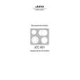
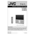
3.1.10 REAR PANEL (1) Loosen 4 screws [ M ]. (2) Remove 4 screws [ N ]. (3) Raise slightly REAR PANEL upward. (4) Take out the REAR PANEL. NOTE : � Before the rear panel is inserted into the cabinet, release the short-circuit between the [SB] connector (1) pin and (2) pin of the DIGITAL INPUT UNIT. (Refer to "CAUTION AT DISASSEMBLY" on Page 14). � After releasing the short-circuit between the [SB] connectors, do not turn the power on until the rear panel is inserted into the cabinet. � Prior to starting the work, be sure to read the following written instructions on the CAUTION LABEL attached to the REAR PANEL. Prior to starting the work, be sure to read the following written instructions on the CAUTION LABEL attached to the REAR PANEL. UNPLUG THE POWER CORD FROM AC OUTLET BEFORE OPEN THE REAR COVER (PANEL). When the rear cover (panel) is removed, follow "CAUTION AT DISASSEMBLY" procedure in the service manual before plugging the TV's power cord into an AC outlet. Failure to follow the procedure will result in PERMANENT damage to some of the television features. 3.1.11 REAR COVER BRACKET (1) Remove 2 screws [ O ]. (2) Take out the REAR COVER BRACKET. 3.1.12 PARTITION � Take out the REAR PANEL. (1) Pull out the PARTITION back ward. 3.1.13 REAR COVER � Take out the SPEAKER GRILLE. � Take out the FRONT CONTROL BOX. � Take out the SCREEN ASS'Y. (1) Remove 2 screws [ P ]. (2) Remove 2 screws [ Q ] from front side. (3) Slightly pull for backside to disengage of the REAR COVER from hooks. (4) Take out the REAR COVER. NOTE : � Because of the large size, at least two persons are recommended for removal and reassemble.
PARTITION
M O N M
REAR PANEL
REAR COVER BRACKET
Fig.6
REAR COVER
Q P
Q
Fig.7
(No.52168)1-15
|
|
|
> |
|