|
|
|
Categories
|
|
Information
|
|
Featured Product
|
|
|
 |
|
|
There are currently no product reviews.
 ;
It took about 24-hours after my payment before I was able to get to the download. Apparently, payment processing is not 100% automated. That is no big deal, just be aware of that going in.
After I got to it, it was in good shape, easy to read, etc. Not some cheap FAX copy looking thing.
Also, this site was the cheapest I found. Another Plus!
 ;
Good price, very legible manual, exactly what I needed -- but had to wait a day to actually get the download of the manual. Would have preferred to download it immediately after payment rather than waiting for someone to "process" my order. I was surprised that I had to wait that long.
;
As the only source for this manual it rather rank quite high since it is well scanned and perfectly readable.
;
the manual is in good quality and it's in pdf. manual was send in less then 24h.
regards
mike
;
I would not plug this machine in without finding a manual like this. In addition to setup and normal operating instructions, it has troubleshooting flowcharts, diagrammed mechanical adjustments, and schematics to beat the band. The tech I hand it to would be thrilled to find solder side PCB diagrams with component outlines superimposed, pinouts for every IC chip, and line drawings of transistors, with labeled legs.
As for printing quality, this may be a copy of a copy, but even the finest print when enlarged is very legible. There is a bit of grayed print over a few pages, as if a wet page were placed over it, but the print is still very legible. If you could borrow an original manual and get it printed and bound for 4 to 6 times the cost, you could get better quality. In that case you wouldn't be here. For price, utility, and availability I am rating this manual highly.
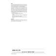
ELECTRICAL ADJUSTMENT
TUNER C.B
FFE801
3
6
IC BLOCK DIAGRAM IC, BU4094BCF
TP6
4
L772 TP1 L981
L771
TP3 TP2 1/3 TP4
IC771 TP5
4
< TUNER SECTION >
1. Clock Frequency Check Settings: � Test point: TP2 (CLK IC771 pin30) Method: Set to AM 1710kHz and check that the test point becomes 2160kHz±45Hz. 2. AM VT Check Settings: � Test point: TP1 (VT) Method: Set to AM 1710kHz and check that the test point is less than 8.5V. Then set to AM 530kHz and check that the test point is more than 0.6V. 3. AM IF Adjustment Settings: � Test point: TP5, TP6 L772 .............................................. 450kHz 4. AM Tracking Adjustment Settings: � Test point: TP5, TP6 � Adjustment location: L981 (1/3) Method: Set to AM 999kHz and adjust L981 so that the test point becomes maximum. 5. FM VT Check Settings: � Test point: TP1 (VT) Method: Set to FM 87.5MHz, 108.0MHz and check that the test point is more than 0.5V (87.5MHz) and less than 8.0V (108.0MHz). 6. DC Balance/Mono Distortion Adjustment Settings: � Test point: TP3, TP4 � Adjustment location: L771 � Input level: 60dB Method: Set to FM 98.0MHz and adjust L771 so that the voltage between TP3 and TP4 becomes 0V±0.04V. Next, check that the distortion is less than 1.3%.
IC, M62431FP
PRACTICAL SERVICE FIGURE
< TUNER SECTION >
<FM SECTION> Signal to noise ratio: Distortion: (Input: 60dB) Stereo separation: Intermediate frequency: <AM SECTION> Sensitivity: (S/N 20dB) Signal to noise ratio: (Input: 74dB) Distortion: Intermediate frequency: More than 62dB (at 98.0MHz) Less than 2.0% (at 98.0MHz) More than 22dB (at 98.0MHz) 10.7MHz
Less than 60dB (at 600kHz) Less than 58dB (at 1000/1400kHz) More than 36dB (at 1000kHz) Less than 1.5% (at 1000kHz) 450kHz
IC, M62439SP
35
36
 $4.99 AVD55 AIWA
Owner's Manual Complete owner's manual in digital format. The manual will be available for download as PDF file aft…
|
|
|
> |
|