|
There are currently no product reviews.
 ;
The service manual was complete and the components on the drawings very good visible.
;
downloaded next day , manual is very helpful , fast and easy
 ;
This Service Manual was exactly what I needed to repair my Philips TV. The purchase was convenient and I received the manual at the same day I paid for it.
;
Very pleased with the whole process. Great commication and very easy instructions to order and to download the manual.
;
It's a good manual, this one it's a scan from the original factory service manual, great quality 100% readeable. definetely it worths what I paid for.
5
6
7
8
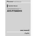
- Removing the Case (Fig.5)
A
3
3 1 3 2 1 3
1 2 3
Remove the two screws and then remove the Holder. Remove the screw.
3
Remove the five screws and then remove the Case.
B
Case
Holder
Fig.5
- Removing the Display Assy (Fig.6)
Motor Unit
Switch
1
Remove the screw.
Disconnect the connector and then remove the Motor Unit.
C
1
2 3
Remove the two screws and then remove the two Holders. Pull out the Display Assy in the arrow indicated direction.
Note) When reassembling, hold the switch down with tweezers or the like and put the Display Assy back to the Chassis. Otherwise, the switch may be damaged and not function properly.
2
2
D
Holder
3
3
Display AssyHolder
Fig.6
- Removing the Main Unit (Fig.7)
Bracket
2 3 3
Shaft Unit
2
E
1
Remove the screw and then remove the Bracket. Remove the four screws and then remove the Shaft Unit. Remove the three screws.
2 3
2
1 3
2
Disconnect the connector and then remove the Main Unit.
Main Unit
Fig.7
F
AVH-P7500DVD/UC
51 7 8
5
6
|