|
There are currently no product reviews.
 ;
THANK YOU FOR A GOOD TRANSACTION, NICE COPY, CLEAR
;
Very Good! All the diagram are easy to read, and its complete.
;
This was an excellent source of detailed assembly information on a device which is at least 12 years old. A very lucky find, coupled with great service.
;
Excellent Service Manual and best price on the Internet. This Service Manual covers everything you could ever need including full circuit schematics, component layout diagrams, stripdown procedure and full parts list/breakdown. I needed this to carry out a modification to one of these headunits and this manual covered everything I needed. Fast delivery, processed within a few hours.
 ;
Thought I would never find a copy of the Technics SX-EN2 Service Manual until I found Owner-Manuals.com. Price was very fair and I received the download promptly. While a photocopy, it is quite readable and includes all the pertinent information and diagrams. Thank you Owner-Manuals!
CX-954
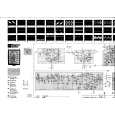
2. The right and left load levers move toward the front part of the mechanical module, to release the locking of the load cam, at the front and rear ends of the levers, with the four shafts of the CRG chassis unit and the shaft of the clamp arm. The right front section of the load cam turns the clamp switch ON, completing the clamp operation.
A shaft (CRG) locked with the cam A shaft (clamp arm) locked with the cam A shaft (CRG) locked with the cam Shafts (CRG) locked with the cam
2.4 Disk eject operation
1. When the loading motor turns in reverse, the disk eject operation begins. 2. The ejection of a 12 cm disk is completed when the SW3 turns OFF, then ON, and then OFF again. 3. The ejection of an 8 cm disk is completed when the SW2 turns OFF, then ON, and then OFF again.
18
|