|
|
|
Categories
|
|
Information
|
|
Featured Product
|
|
|
 |
|
|
There are currently no product reviews.
 ;
Good,readable manual. I found other manuals that were not readable when it came to part ID, but the one downloaded from owner-manual.com was better than expected. I will do buisness with owner-manual.com again.
;
Service Manual that I received was very helpful to me. Thank you.
;
The manual is well organized and is easy to read. The chapters are following normal way to proceed.
;
This scanned manual is well done in that most all the pages except for one is straight and clear- the way I would do them. One page was upside down but that happens. For the money that is charged on this site you get a pretty good deal. Now with complex repairs, I still prefer to us paper manuals which I have to buy at stereomanuals but the one I got here was much less than the $45 he was charging but this is a larger than normal manual for three different units. I am a picky manual user because I have used original manuals from Sony and Teac.
;
Very useful service manual, was exactly what i needed.Good quality,reasonable price.Thank you.
5
6
7
8
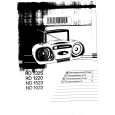
Symptoms in case of poor adjustment: Error efficiency deteriorated: 10 -3 (Optimum value: 10-4 or lower) High jitter of the RF signal RF waveform deformed Unstable operation in tracking closing and servo control Caution: Avoid exposing your eyes to laser beams for a long time. Preparation for adjustment: Clean both ends of the shafts. Use brand new skew screws supplied with the service kit GXX1234. Procedures: 1. Place the DVD mechanism module upside down. To avoid the disc from being robbed when it is turned upside down, first put a coin of about 1.5 mm on the table, then turn the disc upside down and set it so that the 1 in the figure comes to the point immediately above the coin. 2. After replacing the pickup (by referring to the procedures of "Removing the Pickup."), roughly adjust the three skew screws through visual check so that the pickup is mounted in parallel to the CRG chassis around the inner and outer tacks. 3. Connect an oscilloscope as shown in the connecting diagram. 4. Turn on the power of the product. Load the test disc (GGV1018). 5. In the front-end test mode, set the disc type to DVD layer 1. Then, turn on the power. Move the pickup toward the inner tracks. 6. Turn on the laser diodes. 7. With the focus servo closed, complete all automatic adjustments. Close the tracking servo, and then complete all automatic adjustments. 8 Follow the next procedures, from 8-1 to 8-5, and adjust the (three) skew screws. 8-1 Move the pickup toward the inner track and turn the skew adjustment screw C so that the RF level of oscilloscope becomes the maximum. (Tangential adjustment at the inner track position: Adjust the flatness of the disc at the inner track position with the adjustment screw C) 8-2 Move the pickup toward the outer track and turn the skew adjustment screw B so that the RF level becomes the maximum. (Tangential adjustment at the outer track position: Adjust the flatness of the disc at the outer track position with the adjustment screw B) 8-3 Leave the pickup at the outer track position and turn the skew adjustment screws A and B in the same direction alternately one quarter at a time (A�B�A�B ���) so that the RF level becomes the maximum. (Radial adjustment at the outer track position: Keeping the flatness at the outer track position, adjust the flatness of the whole disk with the adjustment screws A and B) 8-4 Move the pickup toward the inner track and turn the skew adjustment screw C so that the RF level becomes the maximum. (Tangential adjustment at the inner track position: Adjust the flatness of the disc at the inner track position with the djustment screw C) 8-5 Repeat the steps from 8-2 to 8-4 three times, and adjust at the position where the RF level becomes the maximum. 9. Turn off the power in the test mode. After confirming that the disc has stopped, eject the disc. 10. Adjust with a screw rock the shaft and skew adjustment screw to the same state as initial one. Skew adj. screw Apply glue Skew adj. screw
A
B
C
D
Prevent applied glue Shaft from extending beyond this position.
Prevent applied glue from extending beyond this position.
E
C 1 B
A
F
AVIC-N2/XU/UC
5 6 7 8
197
|
|
|
> |
|