|
|
|
Categories
|
|
Information
|
|
Featured Product
|
|
|
 |
|
|
There are currently no product reviews.
 ;
Perfect. Received my manual within 24 hours. Clear scan of the manual I needed. No problem.
;
Item as described, very well detailed manual with complete schematics. I've received the download information shortly after payment, very good support.
 ;
Really good and well scanned. File is complete the full service manual for 5$
;
Good product and very helpfull to repair. Many thanks.
;
Very good product. Best service manual. Many thanks
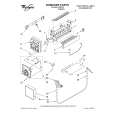
AV-N29303
REPLACEMENT OF CHIP COMPONENT
! CAUTIONS
1. 2. 3. 4. Avoid heating for more than 3 seconds. Do not rub the electrodes and the resist parts of the pattern. When removing a c hip part, melt the s older adequately. Do not reuse a chip part after removing it.
! SOLDERING IRON
1. Use a high ins ulation s oldering iron with a thin pointed end of it. 2. A 30w s oldering iron is rec ommended for easily removing parts.
! REPLACEMENT STEPS
1. How to remove Chip parts # Resistors, capacitors, etc (1) As shown in the figure, push the part with tweezers and alternately melt the solder at each end.
2. How to install Chip parts
# Resistors, capacitors, etc (1) Apply solder to the pattern as indic ated in the figure.
(2) Shift with tweezers and remove the chip part.
(2) Grasp the chip part with tweezers and plac e it on the s older. Then heat and melt the solder at both ends of the chip part.
# Transistors, diodes, variable r esistor s, etc (1) Apply extra solder to each lead.
# Transistors, diodes, variable r esistor s, etc (1) Apply solder to the pattern as indic ated in the figure. (2) Grasp the chip part with tweezers and place it on the solder. (3) First s older lead A as indicated in the figure.
SOLD E R
SOLD E R
A (2) As shown in the figure, push the part with tweezers and alternately melt the solder at each lead. Shift and remove the chip part. B C (4) Then solder leads B and C.
A B Note : After removing the part, remove remaining solder from the pattern. C
No.52006
29
|
|
|
> |
|