|
|
|
Categories
|
|
Information
|
|
Featured Product
|
|
|
 |
|
|
There are currently no product reviews.
 ;
Great service manua!
Always great value and fast service A++++++++++++++++++
;
Excellent Service manual, good quality scans, quick service and very good value. Well reccomended ! All good.
;
Great value service manual!
Good-quality scans. Detailed and valuable informations.
A+++++++++++++++
;
Great value service manual!
Good-quality scans. Detailed and valuable informations.
A+++++++++++++++
;
Excellent scan quality. A complete and very useful manual with all details.
Great service at low price A+++++++++++++++++
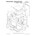
AV-N29304 AV-N29430 2.5 DISASSEMBLY PROCEDURE 2.5.1 (1) (2) (3) (4) 2.5.2 (1) (2) (3) (4) REMOVING THE REAR COVER [AV-N29304] Unplug the power plug. Remove the 11 screws [A] (Fig.1). Remove the 4 screws [B] (Fig.1). Then remove the REAR COVER toward you. REMOVING THE REAR COVER [AV-N29430] Unplug the power plug. Remove the 7 screws [A] (Fig.2). Remove the 4 screws [B] (Fig.2). Then remove the REAR COVER toward you. 2.5.6 CHECKING THE PW BOARD (1) Pull out the MAIN PWB (refer to REMOVING THE MAIN PWB). (2) Erect the MAIN PWB vertically so that you can easily check the backside of the PW Board. CAUTION: � When erecting the chassis, be careful so that there will be no contacting with other PW Board. � Before turning on power, make sure that the wire connector is properly connected. � When conducting a check with power supplied, be sure to confirm that the CRT EARTH WIRE (BRAIDED ASS'Y) is connected to the CRT SOCKET PW board. 2.5.7 WIRE CLAMPING AND CABLE TYING (1) Be sure to clamp the wire. (2) Never remove the cable tie used for tying the wires together. Should it be inadvertently removed, be sure to tie the wires with a new cable tie.
2.5.3 REMOVING THE MAIN PWB � Remove the REAR COVER. (1) Raise this side of the MAIN PWB, and remove the PWB STOPPER [C] from the cabinet. (2) Withdraw the MAIN PWB backward. (If necessary, remove the wire clamp, connectors etc.)
2.5.4 REMOVING THE SPEAKER [AV-N29304] � Remove the REAR COVER. (1) Remove the 4 screws [D], then remove the speaker (Fig.1). (2) Follow the same steps when remove the other hand speaker.
2.5.5 REMOVING THE SPEAKER [AV-N29430] � Remove the REAR COVER. (1) Remove the 4 screws [D], then remove the speaker (Fig.2). (2) Follow the same steps when remove the other hand speaker. NOTE: When removing the 4 screws [D] of the speaker, remove the lower side screw first, and then remove the upper one.
1-6 (No.52129)
|
|
|
> |
|