|
There are currently no product reviews.
 ;
Great product, helped me to restore vintage walkman cassette.
Just some pictures could be little bit more sharp and contrast
Thank you
;
I love older radio's and the service manuals that are sometimes hard to find. Was able to find a manual quite easily on this site.
;
Thank you for your shop manual! Your help was very useful - the device is repaired! Once again - Thank you! I wish you a successful business! Edward (Russia).
;
It was a great experience,instead of purchasing a new Stereo Amplifier ,in just minutes i repaired my old one and that was thaks to the manual I have purchased from you.
Thanks again.
Samuel Alter
;
Das ging ja sehr unkompliziert hat bestens geklappt und die Quallität ist auch noch gut.
Vielen Dank dafür.
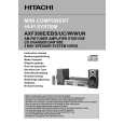
AX-F300
4. Removal of CD Mechanical-Unit Assembly, Main P. W. Board and Motor P. W. Board
(1) Remove one each of screws and from the main P. W. board on the side. (2) Remove 2 screws from the top side of the mechanical unit. (3) Remove 2 screws from the bottom side of the chassis. (4) Remove the connectors , , and of the main P W. board. . (5) Remove the connector of the P T. P W. board. . . (6) Remove 1 screw from the top side of the P T. cover and detach the power transformer from the chassis. . (7) Remove 1 screw of the ground wire. (8) Remove the connectors , and of the motor P W. board from the main P. W. board. . (9) Remove 2 screws from the motor P. W. board. (10) Remove the solder from the four places of the soldering section of the motor. (11) Remove the connectors PG402 and 403 of the motor P W. board. .
PG402 PG403
�7�
|