|
|
|
Categories
|
|
Information
|
|
Featured Product
|
|
|
 |
|
|
There are currently no product reviews.
 ;
Last week I bought a second hand BAUKNECHT TRK4850 DRYER. It is a professional machine with many programs and switch options. I feared it would be a huge quest to find a manual. I was delighted when I found owner-manuals.com. After payment I received the file to download the next day already. The quality is great. I am very happy. Thanks!
but kindly the distributions of the operating programs not find in the owners manual,can you help me to understand the operating programs instructions thank you
;
Very good copy, very readable and easy transaction as always.
;
It is perfect, exactly what we needed. It's like the paper version but less clutter.
 ;
Received my manual within 24 hours. Very clear scan of the manual I needed. Thanks!
;
Very clear scan, I recommend it. Definitely a must have for any 3362 owner.
Alpine could have written a slightly more complete manual, though. It's already pretty huge, but the unit has so many functions, I feel some more explanation would have been better.
Yamaha's manual of their comparable YDSP-1 is a little better in my opinion.
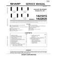
Table Kerf Inserts BA161 WARNING Read and understand the manual for the use of the tool with this accessory.
The kerf insert should be adjusted close to the blade, but without touching the blade, to avoid tear-out on the bottom of the workpiece. 1. 2. Lower the head assembly and lock into position. Loosen the six (6) kerf screws using the Phillips screwdriver (Figure 1). Adjust the kerf inserts as close to the blade (teeth) as possible without touching the blade.
6/12
2/12
Kerf Screws
3.
CM8/12
4/12
12/12
10/12
45
40
4.
Tighten the kerf screws.
5
10
15 2
5
22.5
25 3
0
31
.6
35
Kerf Screws NOTE: At extreme bevel angles the saw blade may slightly cut into kerf insert. Kerf Inserts
10-13a
Figure 1. Kerf Insert
Inserts de Trait de Scie de Table BA161 !
AVERTISSEMENT
Il convient de lire et de comprendre le manuel pour l'utilisation de l'outil avec cet accessoire.
Vis d�encoche Kerf Screws
L�insert d�encoche doit être ajusté à proximité de la lame, mais sans toucher la lame, pour éviter un arrachement sur le bas de l�ouvrage. 1. Abaissez la tête et bloquez en place. 2. Desserrez les six (6) vis d�encoche à l�aide d�un tournevis à empreinte cruciforme (Figure 1). 3. Ajustez les inserts d�encoche aussi près que possible de la lame (dents) sans toucher la lame. 4. Serrez les vis d�encoche. REMARQUE : � des angles extrêmes de biseau, la lame de scie peut couper légèrement dans l�insert d�encoche.
CM8/12
6/12
2/12
12/12
10/12
45
40
4/12
5
10
15 2
5
22.5
25 3
03
31.6
5
Vis d�encoche Kerf Screws
Inserts d�encoche Kerf Inserts
10-13a
Figure 1. Insert d�encoche
Accesorios de Inserción de la Mesa Para la Separación de Corte BA161 !
ADVERTENCIA
Lea y entienda el manual para el uso de la herramienta con este accesorio. Tornillos del accesorio de inserción para la sepKerf Screws aración de corte
El accesorio de inserción para la separación de corte se puede ajustar cerca de la hoja, pero sin tocarla, para evitar que se produzcan desgarrones en la parte inferior de la pieza de trabajo. 1. Baje el ensamblaje del cabezal y fÃjelo en esa posición. 2. Afloje los seis (6) tornillos del accesorio de inserción para la separación de corte usando el destornillador Phillips (Figura 1).
/12 12
C
3. Ajuste los accesorios de inserción para la separación de corte tan cerca de (los dientes de) la hoja como sea posible sin tocar la hoja. 4. Apriete los tornillos del accesorio para la separación de corte. NOTA: En ángulos de bisel extremos la hoja de sierra puede cortar ligeramente en el accesorio de inserción para la separación de corte.
2/12
4/12
M /12 8
10/12
6/12
5
10
15
25
03
31
.6
5
4
45
0
22.5
25 3
Tornillos del accesorio Kerf Screws de inserción para la separación de corte Accesorios de inserKerf Inserts ción para la sepa10-13a ración de corte Figura 1. Accesorio de inserción para la separación de corte
PRINTED IN U.S.A.
2 610 991 819 8/96
|
|
|
> |
|