|
|
|
Categories
|
|
Information
|
|
Featured Product
|
|
|
 |
|
|
There are currently no product reviews.
 ;
The manual you sent me was excellent. It included clear, readable diagrams and a usable parts list. I would surely use your service again. Thanks
;
Payments were processed quickly and items were exactly as described. I will use owner-manuals.com in the future for any other manual needs.
;
The Technics manual was very clear and I was able to solve my technical problems.
I did not think that anyone kept these manuals and was pleasantly surprised to find them on the Internet and at an affordable price.
I would recommend Owner Manuals as a first source of technical products for ‘dated’ equipment manuals.
Ian
;
The content of the manual was not found on the Internet and was a hard find. I check the net for 5 hours until I came across this web-site. When I did find the book it Auto loaded into my IPAD PDF shelf for books for review at anytime. Overall I am satisfied with the book and it answered all my questions. This repair book is obsolete because the product I bout it for is pretty old. Thanks for the help with the download and even having the manual. Thanks 73's K5HRD
;
Excellent manual including schematics. The service was great and the manual helped complete the job.
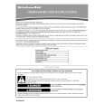
BD-V3000, BD-V3010
AD8323ARU (MAIN ASSY : IC1701)
� UP Stream Amplifier
� Block Diagram
VCC
5,9,10,19,20,23,27
R1
BYP
21
AD8323
15
VOUT+ BUFFER
ATTENUATION CORE
VIN+ DIFF OR SINGLE INPUT AMP POWER AMP
ZOUT DIFF = 75 POWER-DOWN LOGIC
14
VOUT�
VIN�
8 R2
ZIN (SINGLE) = 800 ZIN (DIFF) = 1.6k
DECODE 8 DATA LATCH 8
SHIFT REGISTER
1
DATEN
2
DATA
3
CLK
4,8,11,12,13,16, 6 17,18,22,24,28 PD
GND
7
SLEEP
� Pin Function
PIN FUNCTION DESCRIPTIONS
Pin No. 1
Mnemonic DATEN
Description Data Enable Low Input. This port controls the 8-bit parallel data latch and shift register. A Logic 0-to-1 transition transfers the latched data to the attenuator core (updates the gain) and simultaneously inhibits serial data transfer into the register. A 1-to-0 transition inhibits the data latch (holds the previous gain state) and simultaneously enables the register for serial data load. Serial Data Input. This digital input allows for an 8-bit serial (gain) word to be loaded into the internal register with the MSB (Most Significant Bit) first. Clock Input. The clock port controls the serial attenuator data transfer rate to the 8-bit masterslave register. A Logic 0-to-1 transition latches the data bit and a 1-to-0 transfers the data bit to the slave. This requires the input serial data word to be valid at or before this clock transition. Common External Ground Reference.
2 3
SDATA CLK
4, 8, 11,12, 13, 16, 17, 18, 22, 24, 28 5, 9, 10, 19, 20, 23, 27 6 7 14 15 21 25 26
GND
V CC PD SLEEP OUT� OUT+ BYP V IN+ V IN�
Common Positive External Supply Voltage. A 0.1 F capacitor must decouple each pin. Logic �0� powers down the part. Logic �1� powers up the part. Low Power Sleep Mode. In the Sleep mode, the AD8323�s supply current is reduced to 4 mA. A Logic �0� powers down the part (High Z OUT State) and a Logic �1� powers up the part. Negative Output Signal. Positive Output Signal. Internal Bypass. This pin must be externally ac-coupled (0.1 F cap). Noninverting Input. DC-biased to approximately V CC /2. For single-ended inverting operation, use a 0.1 F decoupling capacitor and a 39.2 resistor between V and ground. IN+ Inverting Input. DC-biased to approximately V CC /2. Should be ac-coupled with a 0.1 F capacitor.
69
|
|
|
> |
|