|
|
|
Categories
|
|
Information
|
|
Featured Product
|
|
|
 |
|
|
There are currently no product reviews.
 ;
Hello.
This paper enable me, to bring this lovley Scope into Function.
Without this Page, i have no cance to make this finish.
Hans M. Knoll Germany
 ;
I used for first time this the wheat and am very thanked
;
This manual was exactly what i needed and could not find elsewhere. Price is not too high. Great !
;
ecelent I was reciver the service manual soon I fell so happy very complete 100% positive all by this store tanks atte Luis salazar
;
A great copy of the manual, and the only one I could find anywhere on the net! The circuit diagrams are easily readable, all component values marked and easy to see. A highly appreciated download!
BE-4140
6. ADJUSTMENT
Perform this adjustment more than 30 minutes after the power is turned on.
7 Equipment used
� � � � � � Spectrum analyzer Oscilloscope Digital voltmeter Video SG Variable resistance attenuator Audio analyzer
BE-4140
DPS Assy
+5V (D) 1 D.GND 6
� FM linear detector � C.W.Signal Generator
Digital Voltmeter
VR1
6.1 DC5V Adjustment
1. Connect the digital voltmeter to CN1004 pin 1 [+5V (D)] and pin 6 [GND (D)] of the DPS ASSY (Connection Diagram 1). +0.02 2. Adjust VR1 of the POWER unit, set to 5.00V - 0.01V
CN1004
POWER Unit
Connection Diagram 1
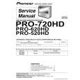
6.2 Adjustment of DPS ASSY (Video SCR ASSY)
� If deviation of the time axis occurs on the oscilloscope screen, or to move the screen to have a better view, perform fine adjustment using a delay. However do not change the ranges of the vertical and horizontal axes. � When reading the waveform on the oscilloscope screen, read the center of the waveform noise. � If the signal waveform on the oscilloscope is difficult to read, adjust the luminance.
DPS ASSY
VIDEO IN CN3001 (J1001)
VR1004 (RV1004) VIDEO OUT CN3002 (J1002) VR1003 (RV1003) IC1021 IC1020
6.2.1 Adjustment of video output pedestal potential
1. Connect the equipment as shown by the dotted lines in Connection Diagram 2. 2. Set the equipment as shown below. a. Oscilloscope 0.1V/div (DC mode) 5µs/div H-SYNC TRG. b. Video SG Staircase signal (1 Vp-p/75�) 3. Set the oscilloscope to the GND mode, and adjust the oscilloscope so that the luminance line is at the center of the oscilloscope. 4. Connect the equipment to the CN3002 (J1002) of the DPS ASSY using a tool as shown by the lines in Connection Diagram 2. 5. Set the unit to the STANDBY mode. The other functions can be set as desired. 6. Set the oscilloscope to the DC mode, and adjust VR1004 (RV1004) in the DPS ASSY so that the pedestal potential of the video waveform satisfies the GND potential set at step 3 (within 0±0.02V).
VIDEO SG
FL1002 IC1016
VR1001 (RV1001) CN1007
Fig.1 Adjustment Locations
BE-4140 Video in DPS ASSY CN3001 (VIDEO SCR ASSY) (J1001) VR1004 (RV1004)
Video out CN3002 (J1002)
OSILLOSCOPE
Staircase signal 1Vp-p/75�
Terminated at 75�
Connection Diagram 2
47
|
|
|
> |
|