|
|
|
Categories
|
|
Information
|
|
Featured Product
|
|
|
 |
|
|
There are currently no product reviews.
 ;
Very useful manuals, somewhere graphics not very clear!
 ;
A great manual; it contained all the information I required and allowed me to restore the receiver to full working condition!
;
Very good expirience with owner-manuals.com.
5 Stars; In future if necessary, i´ll download manuals on this site.
;
Hi - happy with what I received but not quite what I wanted - my fault I assumed that service manual would also include operational instructions which is what I needed - all I needed to know was how to turn the radio - thanks
;
this Manual very important when i buy this Manual i already fix the trouble of my Camera..... thanks keep up the good work.!
PRINTING
18 May, 1999
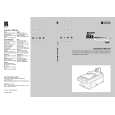
2.2.4 DEVELOPMENT
Overview
[D]
[A]
[E] [C] [B]
G027D535.WMF
This machine uses monocomponent toner, which is composed of resin and ferrite. The toner mixing bar [A] stirs and carries toner to the toner application roller [B]. The toner application roller supplies toner to the development roller [C]. As the development roller turns past the toner metering blade [D], only a thin coating of negatively charged toner particles stays adhered. The diameter of development roller is 16 millimeters and the toner application roller is 12.8 millimeters. During printing, a bias voltage of -650 volts is applied to the toner application roller and another bias voltage of -400 volts is applied to the development roller. The toner is transferred from the toner application roller to the development roller by the potential difference between these two rollers. The exposed area on the drum [E] is at -100 volts. The development roller applies toner to these areas of the latent image as they turn past the drum. At the start and the end of all print process (including the cleaning and initial toner supply modes), 0 volt is applied to the toner application roller, and +250 volts is applied to the development roller. This is to avoid any toner transfer to the drum.
2-10
|
|
|
> |
|