|
|
|
Categories
|
|
Information
|
|
Featured Product
|
|
|
 |
|
|
There are currently no product reviews.
 ;
El producto satisface las necesidades del servicio t
;
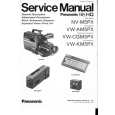
This is a good quality scan of the Operation & Maintenance (Service) Manual for the PAL version of this high-band broadcast umatic, BVU-800P
All schematics and lineup procedures appear to be included in this one manual AFAICT.
The file size is just over 113 MB which gives an idea of the quality and number of pages.
All of the schematics, which contain some fairly small print, are easily readable when you zoom into the page.
John Thompson, Newcastle Upon Tyne, England.
;
Good quality, all schematics of few of models. There is also short form of user manual and regulation manual.
;
Perfect copy of the service manual. you can enlarge every page, and it comes up
with all details.
;
It´s very very nice manual with all, what i need. Original in good quality. Very fast business. Very much thanks...
CHAPTER 1. GENERAL DESCRIPTION
3) With the edge of the SIMM in the slot, roll the SIMM to the left until the hooks [3] at both ends of the slot click into the holes at both ends of the SIMM.
C. SIMM Removal
1) Using the installation tools supplied with the printer, remove the 4 screws [1] and the cover plate [2].
[2]
[3]
[1]
Figure 1-503 Figure 1-504 4) Attach the cover plate [2] and tighten the 4 screws [1]. 2) Gently pull back the two hooks [3] at each end of the SIMM. Roll the SIMM to REFERENCE � When only one SIMM is used, it must be installed in the left slot (SIM601). � When adding two SIMMs, it is easiest to install the first one into the left slot (SIM601).
[3]
the right and remove it.
Figure 1-505 3) Attach the cover plate [2] and tighten the 4 screws [1].
1�37
|
|
|
> |
|