|
|
|
Categories
|
|
Information
|
|
Featured Product
|
|
|
 |
|
|
There are currently no product reviews.
 ;
Very helpfull information and I highly recommend this source for needed information about your products.
 ;
More than pleased with my prurchase, very good product for the price.
;
This is a good quality scan of the service manual which includes an assembly diagram, block diagram, schematic, and parts list. Exactly what is needed to repair my KR-V55R receiver.
;
Excellent concise manual. All needed information was included. Typeface and diagrams were clear. Very fair price considering what others are charging. Many thanks
;
Response is a little slow- I had to wait 12 hours to receive download link but it says that it may take up to 24hrs.
Manual is old and was not produced in PDF- scanned copy is exellent.
Overall- value for money- I recommend
http://getMANUAL.com
2-5. Replacement of Connector Board
2-5-3. BKFD-7009/7009A (HDD unit)
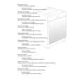
(1) When installing and/or removing the CN-1475 board of the BKFD-7009/7009A (HDD unit) with installed to the FDDR-7000 (Multi-channel digital disk recorder) or the BKFD-7800 (HDD extension box), remove the BKFD-7009/7009A from the FDDR-7000 or the BKFD-7800. (Refer to the section 2-1.) (2) Remove the HDD cover. (Refer to the step (2) of the section 2-2.) (3) Remove the two HDDs. (Refer to the section 2-2.) (4) Remove the fan. (Refer to the section 2-6-3.) (5) Disconnect the one connector (CN3). (6) Remove the four screws and the CN-1475 board.
PWH3 x 5
CN-1475 board PWH3 x 5
CN3
(7) Install the CN-1475 board in the reverse order of the steps (1) through (6).
FDDR-7000 MMP1
2-15(E)
|
|
|
> |
|