|
|
|
Categories
|
|
Information
|
|
Featured Product
|
|
|
 |
|
|
There are currently no product reviews.
 ;
Thought I would never find a copy of the Technics SX-EN2 Service Manual until I found Owner-Manuals.com. Price was very fair and I received the download promptly. While a photocopy, it is quite readable and includes all the pertinent information and diagrams. Thank you Owner-Manuals!
 ;
I really like this manual and it's reliable.I found and bought easly.thank you.
;
Thank you very much. the Instruction corresponds to my expectations. Sent it in time. I don't regret that paid money.
;
Good quality. Quick service. I recommend to everyone.
;
Very good quality scan of the document. I am very pleased with what I got.
2-3. BKNE-1011 2-3-3. Installation and Removal of Boards
2. LD-77 Board (1) Remove the fader grip, the four knobs and the five slide knobs. (Refer to the steps 1 and 2 of the section 2-3-1.) (2) Remove the upper panel assembly. (Refer to the step 3 of the section 2-3-1.) (3) Disconnect the two connectors (CN7 and CN8) on the CPU-207 board. (Refer to the step 4 of the section 2-3-1.) (4) Remove the four screws and the VR fitting bracket. (Refer to the step 6 of the section 2-3-1.) (5) Disconnect the flexible card wire (CN1) on the LD-77 board.
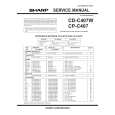
3. SW-871 Board (1) Remove the fader grip, the four knobs and the five slide knobs. (Refer to the steps 1 and 2 of the section 2-3-1.) (2) Remove the upper panel assembly. (Refer to the step 3 of the section 2-3-1.) (3) Disconnect the two connectors (CN7 and CN8) on the CPU-207 board. (Refer to the step 4 of the section 23-1.) (4) Remove the two screws and the ENC bracket. (Refer to the step 5 of the section 2-3-1.) (5) Remove the two screws and disconnect the five connectors (CN1 through CN5). Remove the SW-871 board.
SW-871 board
CN2 CN3 CN1
LD-77 board CN1 Flexible card wire
CN4 CN5
ENC bracket
PSW 3x4
(6) Remove the three screws and the LD-77 board.
B 2.6x4
(6) Install the SW-871 board in the reverse order of the steps (1) through (5).
LD-77 board VR fitting bracket
(7) Install the LD-77 board in the reverse order of the steps (1) through (6).
DNE-1000
2-9(E)
|
|
|
> |
|