|
|
|
Categories
|
|
Information
|
|
Featured Product
|
|
|
 |
|
|
There are currently no product reviews.
 ;
This is a very good quality print (scan) of the original SONY service manual. The original from Sony is on very thin paper. Nevertheless it is very clear and sharp and excellent readable. I'm very satisfied to have now this rare document. I've looking for it many years (infrequent). It contains very detailed circuit diagrams, exploded views, part lists, PCB view with good readable connection lines. Very recommended.
;
A complete manual with all the needed details of calibrations and service instructions about the radio receiver.
A big deal.
Many thanks !
;
Fast delivery and good quality copy. To be recommended
;
Excellent product, very clear print. Detailed circuit and assembly diagrams - this enabled me to repair my CD player with confidence. I highly recommend this site.
;
Fast access, 100% correct and complete service manual
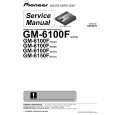
1-7. Main Parts Replacement
1-7-3. Replacing the SY-266 Board
1. Remove the DIF-74 board. (Refer to Section 1-7-2. But no need for the DVBK-1 removal.) 2. Remove the hexagon screws fixed a REMOTE connector. 3. Disconnect the harnesses from the three connectors (CN1, CN2, and CN6) . 4. Remove the two screws from the chassis. 5. Pull the SY-266 board out to the direction of arrow.
Hexagon Screw
1-7-4. Replacing the SW-988 Board
1. Remove the DIF-74 board. (Refer to Section 1-7-2. But no need for the DVBK-1 removal.) 2. Remove the SY-266 board. (Refer to Section 1-7-3.) 3. Remove the screw, and disconnect the harness from the connector (CN2). 4. Unsolder the SW-988 board to remove it.
PWH2.6 x 5
CN2
CN6
Desoldering Portions PWH2.6 x 5
SW-988 Board
PWH2.6 x 5 SY-266 Board CN1 CN2
6. Attach the replacement SY-266 board in the reverse order of step 1 to 5.
5. Attach the replacement SW-988 board in the reverse order of step 1 to 4.
1-6 (E)
BKNW-25
|
|
|
> |
|