|
|
|
Categories
|
|
Information
|
|
Featured Product
|
|
|
 |
|
|
There are currently no product reviews.
 ;
Good Quality of the File.
You get the normal manual is incudet.
;
Very nice and real Service Manual, I didn't thought it actually exist in the real world at all.
 ;
VERY NICE FOR COURTESY AND PRECISION!.
tHE SITE IS VERY IMPORTANT FOR ALL DEVICES
vERY GOOD
;
+++ Is is fine, that was what i looking for. Thanks! +++
;
A very good complete archive, i am very satisfied for document.
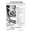
1-4. INSTALLING THE BKP-5972
8. Pass the two coaxial cables through the hole of the chassis. 9. Route the two coaxial cables not to cross each other on the chassis, then bind them by the cable clamp. 10. Connect the coaxial cables to the connectors CN106 on the rear panel.
Cable clamp
[Reference] The signal output from connectors CN2 and CN3 is the same. The coaxial cables can be connected to either connector CN2 or CN3. 13. Insert the BKP-5972 completely. 14. Install the top cover removed in step 2,3 in the reverse order of removal. 15. Tighten the two coin screws and install the front panel.
Coaxial cables
Coaxial cables
CN-106
11. Tighten the four screws to install the rear panel. Note: When installing the rear panel, be careful not to eatch the cables between chassises. 12. Connect the two coaxial cables to connectors CN2 and CN3 of the BKP-5972 in the position where the BKP5972 was inserted into the rail halfway.
Coaxial cables
CN-3 CN-2 AD-130 board
BKP-5972
1-3 (E)
|
|
|
> |
|