|
|
|
Categories
|
|
Information
|
|
Featured Product
|
|
|
 |
|
|
There are currently no product reviews.
 ;
I'm very satisfied with your manual service. Your website made it easy to locate the correct manual. Also the quality is great and I never had a problem reading the fine details.
Thanks again.
Jeff Miller
JM Electronics
 ;
Good quality service manual German user manual. German user manual This is a quality scan of a manual in excellent condition and is just as good as having the original manual in hand
;
The manual for Sony LBT-D505 component stereo system is was excellent , with schematics, parts layout and parts list as well as instructions for adjustments for each component. Print was clear even when enlarged.
;
It's exactly a complete and very useful manual with all details what I needed. Thank you!I will come back whenever I need your manuals or schematics.
;
I searched EVERYWHERE looking for the manual/s on this "extinct" amp. Owner-Manuals.com made it available and for nearly nothing. Thanx to them, I can decipher the unknown cables and sort them out. Thanx, Owner-Manuals.com!!
2-4. Analog Video Gain Adjustment
2-4. Analog Video Gain Adjustment
Measurement Equipment Waveform /vector monitor Procedures 1. Supply 75 % color bars signal of the 4:2:2 component 525/60 serial digital video format to the SDI IN connector. 2. Set S2(A-4) to NTSC. 3. Set S3(A-7) to D1. 4. Check the waveform of the ANALOG MONITOR OUT and adjust 1RV101(D-4) to satisfy the specification.
8. Set S2(A-4) to PAL. 9. Check the waveform of the ANALOG MONITOR OUT to satisfy the specification.
A
Spec. : A = 1.00 ±0.01 Vp-p
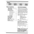
10. Check to see that each luminescent point is placed inside the "4" frame on the vectorscope.
V cy g R Mg
A
YL yl
b U B
G
Cy r
mg
Spec. : A = 140.0 ±1.4 IRE (1.00 ±0.01 Vp-p )
5. Check to see that each luminescent point is placed inside the "4" frame on the vectorscope.
R�Y I R Mg Q
11. Check to see that the image on the video monitor screen is under normal conditions. 12. Supply 75 % color bars signal of the NTSC composite serial digital video format to the SDI IN connector. 13. Set S2 to NTSC. 14. Set S3 to D2. 15. Check the waveform as step 4 and adjust 1RV7(F-7) to satisfy the specification. 16. Check to see that each luminescent point is placed inside the "4" frame on the vectorscope as step 5.
YL B�Y B
�Q
G
Cy �I
17. Supply 75 % color bars signal of the PAL composite serial digital video format to the SDI IN connector. 18. Set S2 to PAL. 19. Check the waveform as step 9 and adjust 1RV8(G-7) to satisfy the specification. 20. Check to see that each luminescent point is placed inside the "4" frame on the vectorscope as step 10.
6. Check to see that the image on the video monitor screen is under normal conditions. 7. Supply 75 % color bars signal of the 4:2:2 component 625/50 serial digital video format to the SDI IN connector.
BKPF-113
2-5(E)
|
|
|
> |
|