|
|
|
Categories
|
|
Information
|
|
Featured Product
|
|
|
 |
|
|
There are currently no product reviews.
 ;
Great price, Quick delivery, the document was very usefull A+++++++++++++++
;
Great price, Quick delivery, the document was very usefull A+++++++++++++++
;
This service Manual for my JVC AV29BF10EES is very helful. Everything is show in detailed diagrams!!!! If you need really good source of information for this type JVC you are on the right place. I am satisfied and very glad for this excellent book. Thank you.
;
Great service, great value like always!!!
Some of the writing is a bit blur but all is usable.
A+++++++++++++++++
;
Great service manua!
Always great value and fast service A++++++++++++++++++
1-2. Electrical Alignment
Preparation 1. Connect the equipment. 2. Extend the APR-30 board using the extension board EX-592. (Refer to �1-6. Use of Extension Board� in the Maintenance Manual for DSM-T1.) 3. Connect the coaxial cable and harness to the APR-30 board. Coaxial cable : CN100 (A-3) Harness (white) : CN900 (A-6) Harness (red)*1 : CN1100 (A-6)
*1 : Only when the rear panel with 5-pin XLR connector is used.
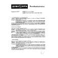
Adjustment Procedures 1. Supply 100% color-bar signal from the composite video signal generator to the VIDEO connector on the DSM-T1. 2. Adjust RV301 (B-4) on the APR-30 board so that VIDEO OUT of the DSM-R1 is satisfied the specification. Adjustment : 1RV301 (B-4) Specification : A = 700 ± 7 mV
4. Return the menu setting data of the DSM-T1 and the DSM-R1 to the factory setting. (Refer to �3. To return the menu setting data to the factory setting� on the page 1-2.) 5. Turn on the power of the DSM-T1 and warm up the unit about 10 minutes. 6. Set the following menu for DSM-T1. (Refer to the �Menu Setup� in the Operation Manual for DSM-T1.) . �03 : VIDEO STD� : 625 7. Set the following menu for DSM-R1. (Refer to the �Menu Setup� in the Operation Manual for DSM-R1.) . �03: VIDEO STD� : 625 8. Set the synthesized signal generator. . Frequency : 1270 MHz . Out Level : 0.0 dBm
A
9
1
6
5
4
8 7
3
A B C D E F G H J K L
RV301
APR-30 board (A side)
1111
2
1-6 (E)
BKSM-T103
|
|
|
> |
|