|
|
|
Categories
|
|
Information
|
|
Featured Product
|
|
|
 |
|
|
There are currently no product reviews.
 ;
Easy and secure way to get a complete service manual of a vintage hifi component. Only some parts of the print copy are dificult to read. Nice price!
 ;
The manual is an excellent reproduction with complete schematics, made troubleshooting and repair a simple process.
;
Up to now you are the BEST! Prompt-efficient and so reasonable ! I have been after SONY service manual for quite some time !Thank you very much ! I can recomend your service to
all my collegagues ! V.Bergfield .
;
This is a very good quality print (scan) of the original SONY service manual. The original from Sony is on very thin paper. Nevertheless it is very clear and sharp and excellent readable. I'm very satisfied to have now this rare document. I've looking for it many years (infrequent). It contains very detailed circuit diagrams, exploded views, part lists, PCB view with good readable connection lines. Very recommended.
;
A complete manual with all the needed details of calibrations and service instructions about the radio receiver.
A big deal.
Many thanks !
1-3. Switching Regulator Replacement 1-4. Fuse/IC Link Replacement
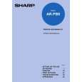
1-3. Switching Regulator Replacement
w Unplug the power supply cord before replacing the switching regulator. n Do not disassemble the switching regulator. 1. Remove the top plate. (Refer to Section 1-1-1.) 2. Raise the wiring clip. 3. Disconnect the connector (CN1). (Refer to Section 11-2.) 4. Remove the two screws (B3x8). 5. Remove the screw (BVTP3x10). 6. Remove the four screws fixing the connectors. 7. Remove the three screws (PSW3x6), then remove the CPU-321/CPU-323 board. 8. Remove the five solders fixing the switching regulator. 9. Remove the switching regulator from the CPU-321/ CPU-323 board.
Switching regulator CPU-321 /CPU-323 board PSW 3x6 Wiring clip PSW 3x6
1-4. Fuse/IC Link Replacement
w A fuse and an IC link is critical parts to safe operation. Replace this component with SONY parts whose part numbers appear in this manual published by SONY. If not, this may cause a fire or electric shock. Be sure to use specified component in this manual. The BKS-R3216/R1617/R1618/R3219/R3220/R1621/ R3240A/R3242A/R3248A has a fuse and an IC link for circuit protection. A fuse and an IC link will blow when abnormality occurs and an overcurrent flows in this equipment. Be sure to replace an old fuse and an IC link with the specified fuse or IC link as shown below after removing the foreign substances that may cause the shorts.
Board CPU-321 CPU-323 IF-803 Ref. No. F1 (A-2) F1 (A-2) PS1 (C-2) PS1 (A-2) Part name H.B.C fuse 2A, 250V H.B.C fuse 2A, 250V IC link, Chip 2A IC link, Chip 0.52A Part No. !1-576-228-11 !1-576-228-11 !1-533-282-21 !1-533-539-11
NOTE: The character in parentheses ( ) indicate the address on board.
Washer
Connector screws BVTP 3x10 B 3x8
n On installing the switching regulator, install it in the reverse order of the removal steps 1 to 9.
1-6 (E)
BKS-R3216/R1617/R1618 BKS-R3219/R3220/R1621 BKS-R3240A/R3242A/R3248A
|
|
|
> |
|