|
|
|
Categories
|
|
Information
|
|
Featured Product
|
|
|
 |
|
|
There are currently no product reviews.
 ;
Very good conversation, Pretty fast Service, wood do it again,
Have paid by Paypal, so i got the Service Manual online after 15 Min.
Very helpfully.
Greeting from Germany,
Hans
;
Good-quality scans. Detailed description. I hope I can repair the machine.
;
High-quality scanning. Detailed description. Recommend for all technician. A+++
;
This is a good quality scan of the original Service Manual from Nordmende, Germany. Contains the circuit diagram, PCB layout, adjust/tune instructions as well. It is NOT in English but in GERMAN language! That was quite right for my german friend from the lower east side in Berlin.
 ;
Received via e-mail this PDF manual is worth the money. This is a quality scan of a manual in excellent condition and is just as good as having the original manual in hand. I have later seen the original manual and it was printed in colour, but this particular manual is black & white but scan resolution is high end quality! All drawings and pictures are presented in great detail. So, nearly perfect score in my opinion.
If you own the turntable you also should own the manual!
1-3. Switching Regulator Replacement 1-4. Fuse/IC Link Replacement
1-3. Switching Regulator Replacement
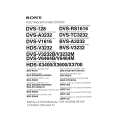
w Unplug the power supply cord before replacing the switching regulator. n Do not disassemble the switching regulator. 1. Remove the top plate. (Refer to Section 1-1-1.) 2. Raise the wiring clip. 3. Disconnect the connector (CN1). (Refer to Section 11-2.) 4. Remove the two screws (B3x8). 5. Remove the screw (BVTP3x10). 6. Remove the four screws fixing the connectors. 7. Remove the three screws (PSW3x6), then remove the CPU-321/CPU-323 board. 8. Remove the five solders fixing the switching regulator. 9. Remove the switching regulator from the CPU-321/ CPU-323 board.
Switching regulator CPU-321 /CPU-323 board PSW 3x6 Wiring clip PSW 3x6
1-4. Fuse/IC Link Replacement
w A fuse and an IC link is critical parts to safe operation. Replace this component with SONY parts whose part numbers appear in this manual published by SONY. If not, this may cause a fire or electric shock. Be sure to use specified component in this manual. The BKS-R3216/R1617/R1618/R3219/R3220/R1621/ R3240A/R3242A/R3248A has a fuse and an IC link for circuit protection. A fuse and an IC link will blow when abnormality occurs and an overcurrent flows in this equipment. Be sure to replace an old fuse and an IC link with the specified fuse or IC link as shown below after removing the foreign substances that may cause the shorts.
Board CPU-321 CPU-323 IF-803 Ref. No. F1 (A-2) F1 (A-2) PS1 (C-2) PS1 (A-2) Part name H.B.C fuse 2A, 250V H.B.C fuse 2A, 250V IC link, Chip 2A IC link, Chip 0.52A Part No. !1-576-228-11 !1-576-228-11 !1-533-282-21 !1-533-539-11
NOTE: The character in parentheses ( ) indicate the address on board.
Washer
Connector screws BVTP 3x10 B 3x8
n On installing the switching regulator, install it in the reverse order of the removal steps 1 to 9.
1-6 (E)
BKS-R3216/R1617/R1618 BKS-R3219/R3220/R1621 BKS-R3240A/R3242A/R3248A
|
|
|
> |
|