|
There are currently no product reviews.
 ;
The manual is useful for trouble shooting for an old instrument. It saved money,and let me enjoy DIY.
 ;
Perfect source of information for replacing the HDD and performing general diagnostics.
;
Perfect source of information for replacing the HDD and performing general diagnostics.
;
Very good scanned copies. Quick response and reasonable price. Thanks for service!
;
Good. Good. Good. Good. Good. Good. Good. Good. Good. Good. Good. Good. Good. Good.
1.4
HOW TO EXAMINE THE BOARDS
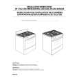
1.4.2 MDA/DC board assembly (1) Remove the top cover to examine the A-side. (2) To examine the B-side, pull down the main board as shown in Fig. 1.4.2 (2).
MDA/DC board assembly DV/CPU board assembly
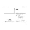
1.4.1 MAIN board assembly (1) Remove the bottom cover to examine the B-side of the main board.
3
Main board assembly
3
Fig. 1.4.1 (1) (2) Remove the four screws 3 to examine the A-side. (3) Remove the two screws 4 on the rear cover. (4) Pull down the main board as shown in fig. 1.4.1 (3).
Fig. 1.4.2 (1)
4
MDA/DC board assembly
REAR COVER
Fig. 1.4.1 (2)
Fig. 1.4.2 (2)
1.4.3 DV/CPU board assembly (1) Remove the top cover as shown in Fig. 1.4.2 (1) to examine the DV/CPU board.
MAIN board assembly Keep a distance to a minimum from the unit, because this FFC cable may be damaged.
Fig. 1.4.1 (3) 1-3
|