|
|
|
Categories
|
|
Information
|
|
Featured Product
|
|
|
 |
|
|
There are currently no product reviews.
 ;
very good manual with clear electrical schemes. Very helpful to find wat was wrong inside my microwave.
 ;
Hi, thankyou for providing the Nordmende Globetrotter original manufacturer's repair manual. Quality is very good and sharp - the PDF file was comfortably small to download. The only question is: why did it take so long to become ready for download?? Many thanks anyway, I fixed the fault in the radio thanks to the circuit.
regards: Nick
;
This was super service.Ordered this manual and was reading the download an hour later
;
as always, rapid and efficient, very good and clear prints
details clearly visible keep going this way!!!!!!
;
I expect a wonderful result as alaways!!!!!!
Usually is much faster....
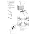
2. Board Replacement
2-1. Board Removal
IDC connectors 1. With the computer powered off, release the catches on both sides of the computer housing cover with fingers and slide the cover out.
Computer Cover
SDDI interface board 1. With the computer powered off, release the catches on both sides of the computer housing cover with fingers and slide the cover out. (Refer to step 1 in the removal of �IDC connectors�) 2. Remove a screw fixing the SDDI interface board (into the lowest slot), and pull out the board.
Catch
2. Disconnect the 20-pin IDC connector from CN1 connector on the Link I/F TRAM board (IF-630). n Link I/F TRAM board (IF-630) is one of the daughterboard installing on SLOT 1 of the TRAM motherboard. 3. Remove a screw fixing the IDC connectors (into the third lowest slot), and pull out the IDC connectors (assembly).
Fixing screw
SDDI interface board
IDC connectors (Assembly)
20-pin IDC CN1 connector connector
Fixing screw TRAM motherboard Link I/F TRAM board (IF-630) [SLOT 1]
2 (E)
BSS-100
|
|
|
> |
|