|
|
|
Categories
|
|
Information
|
|
Featured Product
|
|
|
 |
|
|
There are currently no product reviews.
 ;
Service Manual that I received was very helpful to me. Thank you.
;
The manual is well organized and is easy to read. The chapters are following normal way to proceed.
;
This scanned manual is well done in that most all the pages except for one is straight and clear- the way I would do them. One page was upside down but that happens. For the money that is charged on this site you get a pretty good deal. Now with complex repairs, I still prefer to us paper manuals which I have to buy at stereomanuals but the one I got here was much less than the $45 he was charging but this is a larger than normal manual for three different units. I am a picky manual user because I have used original manuals from Sony and Teac.
;
Very useful service manual, was exactly what i needed.Good quality,reasonable price.Thank you.
;
Acurate informations inside the SM and I could repair my old Sansui SC-3330 without any problems. Thanks.
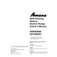
1-5. Replacement of CRT
1-5. Replacement of CRT
1. Loosen the screw of the MIC clamp and open the MIC clamp. 2. Remove the three screws and remove the upper chassis.
Upper chassis
5. Remove the three screws and remove the CRT from the VF tube assembly. 6. Remove the CRT tube from the CRT.
MIC clamp
CRT
PTP2.6 � 8 VF Tube assembly
Lug PTP2.6 � 8 PTP2 � 6
BOLT,HEXAGON SOCKETS 2.6 � 6
7. Remove the four screws and remove the mask spacer. 8. Disconnect the connectors CN21 on LP-84 board and CN31 on LP-85 board.
Mask spacer
3. Disconnect the three connectors CN2, CN4 and anode cable of the VF-60 board. 4. Remove the CRT socket from the CRT.
CRT
Anode cable CRT cable
K2 � 5 LP-84
K2 � 5 CN21
CRT
CN31
LP-85
CN4 VF-60 CN2
9. Install a new CRT in the reverse procedures of removal. n When installing the upper chassis, take care not to clamp the harness between upper and lower chassis.
BVF-10 (UCJ) BVF-10CE (CE)
1-3 (E)
|
|
|
> |
|