|
|
|
Categories
|
|
Information
|
|
Featured Product
|
|
|
 |
|
|
There are currently no product reviews.
 ;
I never been disappointed in my dealings with owners-manuals.com
;
Excellent printing quality. A complete and very useful manual with all details.
;
Even if the PDF is a scan, I can read the information I need.
The price is affordable and the service (mail sending) is very fast.
Thanks ! Regards. William (Fan of Kenwood)
;
Very good quality original datasheet!I like this amazing website!!!!!!
 ;
Excellent just what I needed to replace the electrolytic caps and make this old gem a beauty again. Was as scan of the original photocopied service manual.
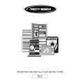
1-5. Replacement of CRT
1. Loosen the screw of the MIC clamp and open the MIC clamp. 2. Remove the two screws (K2.6 X 5). 3. Remove the three hexagonal socket bolts (2.6 X 6) and remove the upper chassis. 4. Disconnect the flexible card wire of the VR-226 board. (How to disconnect the flexible card wire, refer to Section 1-6.)
Upper chassis K2.6 X 5
6. Remove the three screws and remove the CRT from the VF tube assembly. 7. Remove the CRT tube from the CRT.
CRT
PTP2.6 X 8 CRT tube VF tube assembly PTP2.6 X 8 P2 X 6 Lug
Mic clamp
8. Remove the four screws (K2 X 5) and remove the mask spacer. 9. Disconnect the connector CN21 on the LP-101 board.
K2 X 5
Mask spacer
Flexible card wire
LP-101 board
VR-266 board Bolt, hexagon socket 2.6 X 6
CRT
K2 X 5
5. Disconnect the four connectors CN2, CN4, CN5 and anode cable of the VF-67 board.
CN21
Anode cable
CRT
10. Install a new CRT in the reverse procedures of removal. n When installing the upper chassis, take care not to clamp the harness between upper and lower chassis.
CN4
CN2 CN5 VF-67 board
BVF-20W/20WCE
1-3(E)
|
|
|
> |
|