|
|
|
Categories
|
|
Information
|
|
Featured Product
|
|
|
 |
|
|
There are currently no product reviews.
 ;
Very,very good manual.It was very explicit and readble.It was helpfull.Thanks.
;
The service manual is scanned, but high quality, high resolution. The smallest texts on schematics diagram is readable. Super! Thank you!
;
I am satisfied with the service. And if need another manual, i will definitely buy from this site. Keep up the good work.
;
have download a number of manuals todate , most are excellant, one or two sometimes a little difficult to read but a least avaialable, great site .
Brad.
;
Excellent had everything I wanted, very happy with purchase
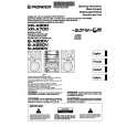
1-5. Replacement of CRT
1. Loosen the screw of the MIC clamp and open the MIC clamp. 2. Remove the two screws (K2.6 X 5). 3. Remove the three hexagonal socket bolts (2.6 X 6) and remove the upper chassis. 4. Disconnect the flexible card wire of the VR-226 board. (How to disconnect the flexible card wire, refer to Section 1-6.)
Upper chassis K2.6 X 5
6. Remove the three screws and remove the CRT from the VF tube assembly. 7. Remove the CRT tube from the CRT.
CRT
PTP2.6 X 8 CRT tube VF tube assembly PTP2.6 X 8 P2 X 6 Lug
Mic clamp
8. Remove the four screws (K2 X 5) and remove the mask spacer. 9. Disconnect the connector CN21 on the LP-101 board.
K2 X 5
Mask spacer
Flexible card wire
LP-101 board
VR-266 board Bolt, hexagon socket 2.6 X 6
CRT
K2 X 5
5. Disconnect the four connectors CN2, CN4, CN5 and anode cable of the VF-67 board.
CN21
Anode cable
CRT
10. Install a new CRT in the reverse procedures of removal. n When installing the upper chassis, take care not to clamp the harness between upper and lower chassis.
CN4
CN2 CN5 VF-67 board
BVF-20W/20WCE
1-3(E)
|
|
|
> |
|