|
|
|
Categories
|
|
Information
|
|
Featured Product
|
|
|
 |
|
|
There are currently no product reviews.
 ;
Ckear manual, well reproduced with plenty of overlap on critical pages.
;
I buy the service manual cheaper here than in elsewhere.Am happy with this site. I recommended the Owner-Manuals.com
;
Great Manual. It was exactly what I was looking for
;
Great Manual. It was exactly what I was looking for
;
I am really satisfied. It was ceap, easy and quick. Te owner manual is a full service book. I got what I expected. Thx
http://getMANUAL.com
4-3. Circuit Boards Location
Part replaced ( ) X BV (14M4DE/20M4DE) C G BC (14M4DE/20M4DE) H
� � � � � � � � � � All voltages are in V. Voltage are dc with respect to ground unless otherwise noted. Readings are taken with a color-bar signal input. Voltage variations may be noted due to normal production tolerance. 2 C512, C513, C523, C549, C592, D501, D533, IC500, IC507, Q500, Q511, R506, R508, R515, R516, R517, R518, R519, R551, R1536, R1537, R1560 ............... (A BOARD) R1536 ( HOLD-DOWN )
Adjustment ( )
1
J Q (Terminal Board) A BB (14M4DE/20M4DE)
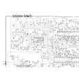
4-4. Printed Wiring Boards and Schematic Diagrams
Note:
� � All capacitors are in µF unless otherwise noted. pF: µµF 50WV are not indicated. Indication of resistance, which does not have one for rating electrical power, is as follows. Pitch: 5 mm Rating electrical power 1/4W � � � � � � � � � Chips resistors are 1/10W. All resistors are in ohms. : nonflammable resistor. : fusible resistor. ¢ : internal component, and adjustment for repair. : panel designation. All variable and adjustable resistors have characteristic curve B, unless otherwise noted. METAL FILM (:RN, :RN-CP) resistors in 1%, 0.50%, 1/4W unless otherwise specified. The components identified by in this basic schematic diagram have been carefully factory-selected for each set in order to satisfy regulations regarding X-ray radiation. Should replacement be required, replace only with the value originally used. When replacing components identified by , make the necessary adjustments indicated. If results do not meet the specified value, change the component identified by and repeat the adjustment until the specified value is achieved. (Refer to R1536 adjust on page 3-9, 3-10) � When replacing the part in below table be sure to parform the related adjustment.
: B+ bus. : B- bus. : signal path. * : Can not be measured. No mark : with PAL co1or-bar signal received or common voltage. For the respective voltage raltage in SECAM, NTSC 3.58, NTSC 4.43, S-VIDEO, and ANALOG RGB modes, see the table. � BV BOARD is non signal. � Circled numbers are waveform references. Reference information RESISTOR : RN METAL FILM : RC SOLID : FPRD NONFLAMMABLE CARBON : FUSE NONFLAMMABLE FUSIBLE : RW NONFLAMMABLE WIREWOUND : RS NONFLAMMABLE METAL OXIDE : RB NONFLAMMABLE CEMENT COIL : LF-8L MICRO INDUCTOR CAPACITOR : TA TANTALUM : PS STYROL : PP POLYPROPYLENE : PT MYLAR : MPS METALIZED POLYESTER : MPP METALIZED POLYPROPYLENE : ALB BIPOLAR : ALT HIGH TEMPERATURE : ALR HIGH RIPPLE
3
Note: The components identified by mark ! are critical for safety. Replace only with the part number specified.
4
�
5
�5�
A B C D E F
�6�
G H
|
|
|
> |
|