|
|
|
Categories
|
|
Information
|
|
Featured Product
|
|
|
 |
|
|
There are currently no product reviews.
 ;
Good quality, all schematics of few of models. There is also short form of user manual and regulation manual.
;
Perfect copy of the service manual. you can enlarge every page, and it comes up
with all details.
;
It´s very very nice manual with all, what i need. Original in good quality. Very fast business. Very much thanks...
;
Purchased the manual that I was looking for at a great price and could download it easily.. Great service experience and for future purchases I plan to use the site.
Thank you very much
;
Exactly what was needed to assess the product - excellent value and great service
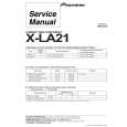
[Dynamic Convergence Adjustment] 1. Minimize the vertical misconvergence in the left-most end of the center of a screen and in the right-most end of the center of a screen by adjusting the DY correction reactor XCV as shown in Fig. 1-15. 2. Minimize the vertical misconvergence in the top of a screen and in the bottom of a screen by adjusting the DY correction reactor YCH as shown in Fig. 1-15. 3. Minimize the vertical misconvergence in the top of a screen and in the bottom of a screen by adjusting the DY correction reactor TLV as shown in Fig. 1-15. 4. Minimize the vertical misconvergence in the left-most end of the center of a screen and in the right-most end of the center of a screen by adjusting the DY correction reactor TLH as shown in Fig. 1-15.
XCV YCH B B G R B R B R G R
[G2 Adjustment] 1. Connect the 480/60i entire black signal to the ANALOG Y/G input connector. 2. Connect an oscilloscope probe one after another to the C board R-cathode (TP701), G-cathode (TP702) then B-cathode (TP703) to measure the DC voltage at their respective pedestal portion. 3. Connect an oscilloscope to the cathode whose DC voltage of the respective pedestal portion has the highest DC voltage. 4. Adjust RV702 on the C board so that the DC voltage of the respective pedestal portion is 125 ± 3 V.
Pedestal
125±3(VDC)
TLV R G B
TLH
0(VDC)
Fig. 1-16
B G R R GB B GR
Fig. 1-15
BVM-D14H1U/D14H5U/D14H1E/D14H5E/D14H1A/D14H5A
3-11
|
|
|
> |
|