|
|
|
Categories
|
|
Information
|
|
Featured Product
|
|
|
 |
|
|
There are currently no product reviews.
 ;
Manual acquired with good resolution, complete in all its pages, very good policy of the folder where are saved all products purchased.
 ;
Service manual very complete and clear. It was very helpfull for my work.
;
This is the 2nd time I download manuals from this website and I can say it's what I was expecting. It contains schematic, layout (decent quality), short description, parts and dissasembly instructions. I recomend it for anyone who wants to repair/modify this device.
;
Very useful Service Manual! With it I was able to identify the damaged pots in my old amplifier, purchase the adequate replacements and make myself the repair.
I have again my old amplifier, still a very good one that I will keep for as many years as I can!
Thanks to Owner Manuals!
;
Good price for the manual and easy to locate on the site and download. Plus, just like the original. Thanks a lot.
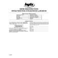
[Dynamic Convergence Adjustment] 1. Minimize the vertical misconvergence in the left-most end of the center of a screen and in the right-most end of the center of a screen by adjusting the DY correction reactor XCV as shown in Fig. 1-15. 2. Minimize the vertical misconvergence in the top of a screen and in the bottom of a screen by adjusting the DY correction reactor YCH as shown in Fig. 1-15. 3. Minimize the vertical misconvergence in the top of a screen and in the bottom of a screen by adjusting the DY correction reactor TLV as shown in Fig. 1-15. 4. Minimize the vertical misconvergence in the left-most end of the center of a screen and in the right-most end of the center of a screen by adjusting the DY correction reactor TLH as shown in Fig. 1-15.
XCV YCH B B G R B R B R G R
[G2 Adjustment] 1. Connect the 480/60i entire black signal to the ANALOG Y/G input connector. 2. Connect an oscilloscope probe one after another to the C board R-cathode (TP701), G-cathode (TP702) then B-cathode (TP703) to measure the DC voltage at their respective pedestal portion. 3. Connect an oscilloscope to the cathode whose DC voltage of the respective pedestal portion has the highest DC voltage. 4. Adjust RV702 on the C board so that the DC voltage of the respective pedestal portion is 125 ± 3 V.
Pedestal
125±3(VDC)
TLV R G B
TLH
0(VDC)
Fig. 1-16
B G R R GB B GR
Fig. 1-15
BVM-D14H1U/D14H5U/D14H1E/D14H5E/D14H1A/D14H5A
3-11
|
|
|
> |
|