|
|
|
Categories
|
|
Information
|
|
Featured Product
|
|
|
 |
|
|
There are currently no product reviews.
 ;
Excellent Service Manual and best price on the Internet. This Service Manual covers everything you could ever need including full circuit schematics, component layout diagrams, stripdown procedure and full parts list/breakdown. I needed this to carry out a modification to one of these headunits and this manual covered everything I needed. Fast delivery, processed within a few hours.
 ;
Thought I would never find a copy of the Technics SX-EN2 Service Manual until I found Owner-Manuals.com. Price was very fair and I received the download promptly. While a photocopy, it is quite readable and includes all the pertinent information and diagrams. Thank you Owner-Manuals!
;
I really like this manual and it's reliable.I found and bought easly.thank you.
;
Thank you very much. the Instruction corresponds to my expectations. Sent it in time. I don't regret that paid money.
;
Good quality. Quick service. I recommend to everyone.
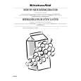
[Dynamic Convergence Adjustment] 1. Minimize the vertical misconvergence in the left-most end of the center of a screen and in the right-most end of the center of a screen by adjusting the DY correction reactor XCV as shown in Fig. 1-15. 2. Minimize the vertical misconvergence in the top of a screen and in the bottom of a screen by adjusting the DY correction reactor YCH as shown in Fig. 1-15. 3. Minimize the vertical misconvergence in the top of a screen and in the bottom of a screen by adjusting the DY correction reactor TLV as shown in Fig. 1-15. 4. Minimize the vertical misconvergence in the left-most end of the center of a screen and in the right-most end of the center of a screen by adjusting the DY correction reactor TLH as shown in Fig. 1-15.
XCV YCH B B G R B R B R G R
[G2 Adjustment] 1. Connect the 480/60i entire black signal to the ANALOG Y/G input connector. 2. Connect an oscilloscope probe one after another to the C board R-cathode (TP701), G-cathode (TP702) then B-cathode (TP703) to measure the DC voltage at their respective pedestal portion. 3. Connect an oscilloscope to the cathode whose DC voltage of the respective pedestal portion has the highest DC voltage. 4. Adjust RV702 on the C board so that the DC voltage of the respective pedestal portion is 125 ± 3 V.
Pedestal
125±3(VDC)
TLV R G B
TLH
0(VDC)
Fig. 1-16
B G R R GB B GR
Fig. 1-15
BVM-D14H1U/D14H5U/D14H1E/D14H5E/D14H1A/D14H5A
3-11
|
|
|
> |
|