|
|
|
Categories
|
|
Information
|
|
Featured Product
|
|
|
 |
|
|
There are currently no product reviews.
 ;
5 STARS for FAST DELIVERY, BEST PRICES and QUALITY PRODUCT. Item was exactly as described with superb resolution. Will definitely source all my future requirements from this website. Thanks a lot owner-manual.com!
;
OEM manual provided all schematics, board layouts and component specs necessary to facilitate unit maintenance. All pages were clear and readable.
;
Good condition and quality. Hard to find anywhere in Internet, only on this site.
 ;
Exactly what I needed to be able to bring the amp back to life... will come back to this site the next time I need schematics.
;
Information was accurate and very helpful.
However the continuity made it a little difficult to follow from one page to the next.
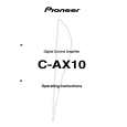
C-AX10
When the front flip-down door is opened
0-=
~ !@ # $
DOLBY
DIGITAL
%^ &*()_ + ¡ �
% CHARACTER INPUT buttonV This button is used to enter the Character Input mode for changing the input signal or sound memory setting to a user-selected name. ^ Digital REC Selector button (REC SELECTOR [DIGITAL] )V This button is used to enter the mode for selecting the REC OUT signal that is output from the digital output jack. & INPUT GAIN buttonV This button is used to enter the mode for adjusting the analogue input and digital input gain. * PARAMETER CHECK buttonV This button is used to enter the mode for checking the current settings. ( Tone Control button (TONE)V This button is used to enter Tone Control mode. ) Tone Control Channel button (EACH/ALL)V This button is used to switch between EACH mode and ALL mode. ÷ EACH mode : The front, centre, and surround channels can each be set individually. ÷ ALL mode : The front, centre, and surround channels are set to the same settings.
_ Balance Control button (BALANCE) V This button is used to enter the mode for adjusting the balance of the front left and right channels. + SYSTEM SET UP buttonV This button is used to enter System Setup mode for speaker setup or selecting modes. ¡ NETWORK SET UP buttonV This button is used to enter Network Setup mode when the OUTPUT MODE selector (�) is set to Digital Network FIR mode or Digital Network IIR mode. � OUTPUT MODE selector This selector is used to set to one of the following four modes. ÷ Digital Network FIR mode ÷ Digital Network IIR mode ÷ Normal mode ÷ OFF (Output off)
V After pressing the buttons in % to ¡, use the MULTI CONTROL jog dial 8 to make the settings and adjustments.
114
|
|
|
> |
|