|
|
|
Categories
|
|
Information
|
|
Featured Product
|
|
|
 |
|
|
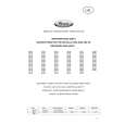
There are currently no product reviews.
 ;
It's a good manual, this one it's a scan from the original factory service manual, great quality 100% readeable. definetely it worths what I paid for.
 ;
A good manual! fast service and good qualityi for pdf document.
thanks!
;
Very helpful and complete manual. Maybe only one negative is schematics have sometimes unreadable name of the parts. But it's not a big problem.
;
Excellent high quality schematics brought my old Heidelberg back to life. Fast download at a reasonable price. Thanks.
;
This document is just what I was looking for, it´s very useful, it contains adjustment procedures for the final stage of the power amp and also
has a complete wiring diagram and description of the main semiconductors used in the design.
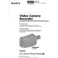
1-1-2. Precautions 1. Switch settings Adjust the switches to the following positions without loading the cassette tape unless otherwise specified. 1) Camera/video power switch Operation switch block ·············································· Camera 2) PROGRAM AE switch (CF-44 board S416) ··············· AUTO 3) D ZOOM switch (MENU) ··············································· OFF 4) STEADY switch (CF-44 board S403) ····························· OFF 2. Adjustment sequence Adjust in the given order. 3. Subject 1) Set the camera and pattern box as shown in Fig. 6-1-2. 2) Color bar chart (Standard picture frame) � Adjust the picture frame as shown in Fig. 6-1-3. � Adjust camera zooming and direction until the camera output waveform on the oscilloscope shown in Fig. 6-1-3 (a) and the color picture on the monitor TV shown in Fig. 6-1-3 (b) have been acquired. � Maintain this setup until adjustment is complete.
3)
White pattern (Standard picture frame) Remove the color bar chart from the pattern box and adjust the camera setup until the white pattern picture frame is the same size and same position as the color bar chart (the standard picture frame).
Fig. 6-1-2
Adjust camera zooming and direction to obtain the output waveform shown in Fig. �a� and the TV monitor display shown in Fig. �b�. Fig. 6-1-3 4) Chart for flange back adjustment Join together a piece of white A0 size paper (1189mm � 841 mm) and a piece of black paper to make the chart shown in Fig. 6-1-4.
Note : Use a non-reflecting and non-glazing vellum paper. The size must be A0 or larger and the joint between the white and black paper must not have any undulations.
Fig. 6-1-4
6-2
|
|
|
> |
|