|
|
|
Categories
|
|
Information
|
|
Featured Product
|
|
|
 |
|
|
There are currently no product reviews.
 ;
FAST very good and clear a great unexpensive job!!! very recomended for all people who are preofessional or hobbists as me!!!!!!
 ;
Thank you very much for this Service Manual, it helped us a lot to repair the M-4318!
...BUT: The parts list is missing and the free parts katalog on web isn't complete, so now we don't know the part numbers of the defect parts :(
We had to build them out of a working machine, and need the numbers to reorder the missing parts now.
;
Very good manual with clear electrical diagrams. Thanks owner-manuals.
;
Great manual, thank you, sony kp46s3 service manual perfectly, i am very happy.
;
Complete original Service Manual in good (scan) quality!
SERVICE NOTE
1. POWER SUPPLY DURING REPAIRS
In this unit, about 10 seconds after power is supplied (8.4V) to the battery terminal using the service power cord (J-6082-223-A), the power is shut off so that the unit cannot operate. This following three methods are available to prevent this. Take note of which to use during repairs. Method 1. Connect the servicing remote commander RM-95 (J-6082-053-B) to the LANC jack, and set the remote commander switch to the �ADJ� side. Method 2. Press the battery switch of the battery terminal using adhesive tape, etc. Method 3. Use the DC IN terminal. (Use the AC power adaptor.)
DC IN terminal Battery SIG terminal Battery terminal �
Battery switch
Battery terminal �
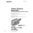
2. TO TAKE OUT A CASSETTE WHEN NOT EJECT (FORCE EJECT)
1 Refer to 2-1. to remove the front panel block. 2 Refer to 2-4. to remove the cabinet (R) assembly. 3 Refer to 2-6. to remove the battery panel block. 4 Refer to 2-7. to remove the cabinet (L) block. 5 Add +5V from the DC POWER SUPPLY and unload with a pressing the cassette lid.
6
Pull the timing belt in the direction of arrow A with a pinsette while pressing the cassette lid (take care not to damage) to adjust the bending of a tape.
A
Pinsette
Press the cassette lid not to rise the cassette compartment [DC power supply] (+5V)
Timing belt
7
Let go your hold the cassette lid and rise the cassette compartment to take out a cassette.
+
�
Loading motor Adjust the bending of a tape
Timing belt
�5�
|
|
|
> |
|