|
|
|
Categories
|
|
Information
|
|
Featured Product
|
|
|
 |
|
|
There are currently no product reviews.
 ;
Paid for service manual & got the download fast - worth a visit if you need a service manual
;
It's the manual, I am searching for. Now I am able to repair my Braun A501.
 ;
Great service manual. Unfortunately on page no. 41 there are some details which i can't read.
;
Wonderful service... doubt that I could have made the repairs to my turntable without this service manual. Great help!
Well worth the price paid!
;
nice completed SERVICE MANUAL as the description THANK YOU !!!-
SERVICE NOTE
1. POWER SUPPLY DURING REPAIRS
In this unit, about 10 seconds after power is supplied (8.4V) to the battery terminal using the service power cord (J-6082-223-A), the power is shut off so that the unit cannot operate. This following three methods are available to prevent this. Take note of which to use during repairs. Method 1. Connect the servicing remote commander RM-95 (J-6082-053-B) to the LANC jack, and set the remote commander switch to the �ADJ� side. Method 2. Press the battery switch of the battery terminal using adhesive tape, etc. Method 3. Use the DC IN terminal. (Use the AC power adaptor.)
DC IN terminal Battery SIG terminal Battery terminal �
Battery switch
Battery terminal �
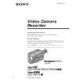
2. TO TAKE OUT A CASSETTE WHEN NOT EJECT (FORCE EJECT)
1 Refer to 2-1. to remove the front panel block. 2 Refer to 2-4. to remove the cabinet (R) assembly. 3 Refer to 2-6. to remove the battery panel block. 4 Refer to 2-7. to remove the cabinet (L) block. 5 Add +5V from the DC POWER SUPPLY and unload with a pressing the cassette lid.
6
Pull the timing belt in the direction of arrow A with a pinsette while pressing the cassette lid (take care not to damage) to adjust the bending of a tape.
A
Pinsette
Press the cassette lid not to rise the cassette compartment [DC power supply] (+5V)
Timing belt
7
Let go your hold the cassette lid and rise the cassette compartment to take out a cassette.
+
�
Loading motor Adjust the bending of a tape
Timing belt
�5�
|
|
|
> |
|