|
|
|
Categories
|
|
Information
|
|
Featured Product
|
|
|
 |
|
|
There are currently no product reviews.
 ;
Excellent service and prompt delivery. But it's not a manual - only 4 pages wiring diagrams.
Thanks.
 ;
The manual I purchased was exactly what I needed to repair my Toshica television. The manual contained schematics and troubleshooting information that was very helpful.
;
Il download del Service Manual JVC HR 4100 non é stato eseguito
;
The Service Manual was just as expected, complete with schematics and I was able to download it in less than an hour after I ordered it. The only problem with these is that the schematics are hard to read due to the small font. I could remedy this by printing them on a larger printer.
;
Very fast, clear and usefull site !
Also this Service Manual are very well maked and with a very good definition !
Very fast download speed !
Recomended Seller !
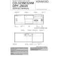
CD-323M/324M/DPF-J5020
CIRCUIT DESCRIPTION
3. TEST MODE
INPUT KEY Insert the AC plug to the wall outlet with pressing the SKIPDOWN key. PROCEDURE INITIAL CONDITION � Disc No.1 moves to the center and clamp it. � Clear the memory of the SRAM. � Door opens. � Set the switch of TIMER ON PLAY to ON. � Set the switch of SYSTEM CONTROL to XS8. CIRCUIT ADJUSTMENT � Open the door and load the disc to the Disc No.1. � Close the door. The unit chances to test mode �05� after clamping the disc. Change the mode 05(tracking-on) and 03 (tracking-off) alternately by the PLAY key. Stop the function. The pickup travels outwards. The pickup travels inwards. Shows the result of self-adjustment. 07 EF/FB à ó 08 TG/FG ó 09 FE/RF ó 10 TE/VC ìì Mode changes alternately by the RANDOM key. � Check the transmission signal (Disc No.1 and Track No.99) of the remote controller. *DPF-J5020, CD-324M only. Playback PGM signal of the Track No.7,13,23,30,34 and 41 in the order. And release Release the test mode. Check the switch position. Check the switch position. Check the SL16-TEXT port. �TxD : H - RxD:L, TxD:L - RxD:H� CHECK THE MECHANISM JAMMING. the order. Clamp the Disc No1,2,100,50,200 and 199 in the order. THE MECHANISM TEST MODE. Display shows NIAGARA until pressing any key. Change the mode 05 (tracking-on) and 03 (tracking-off) alternately by the PLAY key. Stop the function. Shows the result of self-adjustment. 07 EF/FB à ó 08 TG/FG ó 09 FE/RF ó 10 TE/VC ìì Mode changes alternately by the STOP key. Arm Motor Load operation. Arm Motor Unload operation. Rotary Motor Clockwise turning. Rotary Motor Counterclockwise turning. DISPLAY INITIAL OK!! MECH. INITIAL INITIAL NG TIMER, NG SER, NG TEST ON
Insert the AC plug to the wall outlet with pressing the REPEAT key PLAY/PAUSE STOP UP DOWN RANDOM
05 1 : 23
03 2 : 34
00 MOTOR FORWARD MOTOR REVERSE 07 XXX:XXX 08 XXX:XXX 09 XXX:XXX 10 XXX:XXX NG : blinking shows niagara mode
DISPLAY POWER
REPEAT CONFIRM (TIMER PLAY SW) (SL16/XS8 SW) (TxD port) Insert the AC plug to the wall outlet with pressing the UP key. Insert the AC plug to the wall outlet with pressing the RANDOM key. PLAY/PAUSE STOP
TIMER ON, TIMER OFF 16BIT, 8BIT
05 1 : 23
03 2 : 34
07 XXX:XXX 08 XXX:XXX 09 XXX:XXX 10 XXX:XXX NG : blinking MOTOR LOAD MOTOR UNLOAD MOTOR CW MOTOR CCW
UP DOWN RANDOM DISPLAY
7
|
|
|
> |
|