|
|
|
Categories
|
|
Information
|
|
Featured Product
|
|
|
 |
|
|
There are currently no product reviews.
 ;
The Service Manual for the Kenwood KR-V55R provided by owner-manuals.com was as described/advertised. The contents provided the necessary information to effect a diagnosis of the unit. The schematics above all else was instrumental in tracing the the signal flow from component to component.
 ;
This manual was the factory original. Excellent value and contained all the details I needed. Easy dowwnload provided the information when I needed it.
;
Impeccable, document très complet. Perfect, i get all i need. All schematic are correct. Thanks
;
The manual is of better quality compared to other. I found it less expensive and therefore it it is the best buy cost vs quality.
;
I bought the service-manual of the sony ICB-1020(an old transmitter-receiver) at "www.Owners-Manual.com", I found the service-manual for a fairly cheap price(in comparison with other sellers). I filled in some questions, payed the order with Ideal, and within 24 hours I had my service manual. I was very happy:In no time I had my service-manual and everything, but literally everything was noted down in the manual; the electronic scheme, the parts list, etcetera.
A very practical, reference-document.
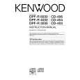
CD-403/403-S/404/406/DPF-R3030/R3030-S/R4030/R4030-S/R6030
ADJUSTMENT
No. ITEM INPUT SETTINGS OUTPUT SETTINGS PLAYER SETTINGS ALIGNMENT POINTS ALIGN FOR FIG.
Open the tray (Normal mode), then turn the power off. While pressing the REPEAT key, turn the AC ON. (Test mode) Press the PLAY/PAUSE key, then confirm that the display is "03". On the power from 0.08 to 0.15 mW, when the diffraction grating is correctly aligned with the RF level of 1.0 Vp-p or more.
1
LASER POWER
�
Apply the sensor section of optical power meter on the pickup lens.
�
(a)
1. Load a disc on disc 1 tray. 2. Turn the power off. 3. While pressing the REPEAT. key, turn the power ON to enter the Test mode. Connect an oscilloscope as follows. CH1: Connect the DC voltmeter to CN3(pin3 and 4) on X32. Press the PLAY/PAUSE key, then confirm that the display is "05". Press the PLAY/PAUSE key, then confirm that the display is 03 or 05.
1
FOCUS ERROR BIAS
Test disc Type 4
FE BIAS VR1
Optimum eye pattern
2
LASER CURRENT CHECK
Test disc Type 4
-
0.5±0.2V
Note: Type 4 disc : SONY YEDS-18 Test Disc or equivalent. LPF: Around 47 k�+ 390 pF or so. Step 1~4 are in Test Mode.
(a) Laser power
0.08~0.15 mW
Pickup
Optical power meter
5
|
|
|
> |
|