|
|
|
Categories
|
|
Information
|
|
Featured Product
|
|
|
 |
|
|
There are currently no product reviews.
 ;
Very nice to have! Now it is no problem to understand how it is put together.
Helps me a lot.
;
good scans, all is clear. all pages in order. recommended
 ;
Très-très bon site, facile, très bon prix.
Au futur besoin, je n’hésiterais à faire appel à vous.
Merci
;
This is the correct service manual of SHARP RX-100H(BK) DAT.
;
The ervice manual for my 1982 Kenwood KR-1000 receiver is great! Full detail on all circuits with part number detail. I will definately be ordering more manuals for my other vintage equipment! Order was fulfilled quickly! Very efficient ordering process! Thnaks for your help! Great site!
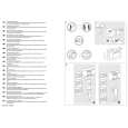
DISASSEMBLY INSTRUCTIONS
1. Using the unlock key that came with the unit or a similar tool, unlock the Mounting Box and remove toward the rear of the unit. 2. Remove the screw (A) located on the rear of the top cabinet and remove the Top Cabinet. 3. Remove two screws (B) located on the rear of the bottom cabinet then remove the Bottom Cabinet. 4. Remove two screws (C) (one located at the left side and one located at the right side of the Front Bracket) then remove the Hooks. 5. Remove the Front Panel and the Ring. 6. Remove two screws (D) from each side of the base then remove the Base. 7. Remove two screws (E) from the front bracket and remove two screws (F) from the rear cabinet. 8. Remove two screws (G) from the front deck bracket then remove the Front Deck Bracket. Remove two screws (H) from the rear deck bracket then remove the Deck and the Rear Deck Bracket. 9. Remove the screw (I) and three screws (J) from the Heat Sink then remove the Heat Sink and the K7377 Heat Sink. 10. Remove the screws (K) and remove the Antenna Clip. Remove the screw (L) and remove the Wire Clip. 11. Remove two screws (M) from the rear cabinet of the right side then remove the IC7805 Bracket. 12. Remove five screws (N) from the main board then remove the Main Board.
13.
Remove four screws (O) from each side of the rear cabinet then remove the Front Bracket and the Rear Cabinet.
3
|
|
|
> |
|