|
|
|
Categories
|
|
Information
|
|
Featured Product
|
|
|
 |
|
|
There are currently no product reviews.
 ;
El producto satisface las necesidades del servicio t
;
This is a good quality scan of the Operation & Maintenance (Service) Manual for the PAL version of this high-band broadcast umatic, BVU-800P
All schematics and lineup procedures appear to be included in this one manual AFAICT.
The file size is just over 113 MB which gives an idea of the quality and number of pages.
All of the schematics, which contain some fairly small print, are easily readable when you zoom into the page.
John Thompson, Newcastle Upon Tyne, England.
;
Good quality, all schematics of few of models. There is also short form of user manual and regulation manual.
;
Perfect copy of the service manual. you can enlarge every page, and it comes up
with all details.
;
It´s very very nice manual with all, what i need. Original in good quality. Very fast business. Very much thanks...
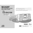
CD-BA3100
(2) Tracking system check Check the TE waveform at pin 15 on IC1.
If the waveform shown in Figure 50-1 appears and soon after NO DISC appears. ? No "Initialization" is possible, but play is not possible. ? No Yes The tracking servo is not activated. Check the peripheral circuits at pins 14, 15 and 20 on IC1, and CNS1A/B.
Yes
A normal jump operation cannot be completed or the beginning of the track cannot be found. Check the around pin 20 on IC1.
"Initialization" is not possible.
Data cannot be read. Check the VCO-PLL system.
Stopped
CH1=10V DC 10:1
T
CH2=1V DC 10:1
100ms/div (100ms/div) NORM:100kS/s
TE
2
T 1
DRF
=Filter= Smoothing : ON BW : FULL
=Offset= CH1 : 0.0V CH2 : 0.00V CH3 : 0.00V CH4 : 0.00V
=Record Length= Main : 100K Zoom : 2K
=Trigger= Mode : NORMAL Type : EDGE CH1 Delay : 2.924ms Hold off : 0.2µs
Figure 50-1 (3) Spin system check
Press the Disc 1~6 switch without inserting a disc, and then try starting the play operation.
1. The turntable rotates a little. ? (Waveform drawing Figure 50-2) No 2. The turntable doesn't rotate.
The spin driver circuit is OK. Yes
Check around pin 22 on IC1, pins 26 and 27 on IC2, and CNS3A/B.
Stopped CH1=200mV DC 10:1
T
CH2=500mV DC 10:1
1999/04/07 09:51:15 500ms/div (500ms/div) NORM:20kS/s
T
FDO
2
1
SPDO
=Filter= Smoothing : ON BW : FULL
=Offset= CH1 : 0.000V CH2 : 0.000V CH3 : 0.00V CH4 : 0.00V
=Record Length= Main : 100K Zoom : 2K
=Trigger= Mode : NORMAL Type : EDGE CH2 Delay : 2.924ms Hold off : 0.2µs
Figure 50-2
� 50 �
|
|
|
> |
|