|
|
|
Categories
|
|
Information
|
|
Featured Product
|
|
|
 |
|
|
There are currently no product reviews.
 ;
It's complete and helpful manual with good quality of scan. Thanks very much.
;
The service was quick and simple, finding the service manual easy and it appears to be the original with colour schematics. It contained the info I was after and so sorted the problem.
I have copied it to CD and attached the envelope to the inside back cover of the owners manual. Good manual and excelent service. Robin Wood, Wood Electronics, New Zealand.
;
Exactly what was needed to assess the product - excellent value and great service
 ;
Nice to have the service manual for the Sony DCR-TRV345E now. The document is of excellent quality.
;
MACKIE HR824 26 pages English-only Service Manual contains:
1) HR824 technical overview with the description of front and rear panel switches.
2) HR824 specs
3) Block Diagram
4) Wiring Diagram
5) Packaging management
6) Spare part & final assembly list (for PCB rev A and B) + exploded view
7) Test Procedures (where, how to measure voltage...) including Test Point diagram on the PCB.
8) IC and Transistor charts.
Excellent guide: very clear, good scan quality enabling us to print readable diagram :-)
Note:
Mackie HR824 make extensive use of surface mount devices (SMD). Service on the HR824 must
only be undertaken by experienced service technicians with the right tools, experience and patience to perform surface mount rework when needed.
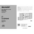
CD-BK100W/CD-BP90W
DISASSEMBLY
Caution on Disassembly Follow the below-mentioned notes when disassembling the unit and reassembling it, to keep it safe and ensure excellent performance: 1. Take cassette tape and compact disc out of the unit. 2. Be sure to remove the power supply plug from the wall outlet before starting to disassemble the unit. 3. Take off nylon bands or wire holders where they need to be removed when disassembling the unit. After servicing the unit, be sure to rearrange the leads where they were before disassembling. 4. Take sufficient care on static electricity of integrated circuits and other circuits when servicing. CD-BK100W/CD-BP90W
STEP 1 2 3 REMOVAL Top Cabinet Side Panel (Left/Right) CD Tray Cover/ CD Player Unit PROCEDURE 1. Screw ...................... (A1) x4 1. Screw ...................... (B1) x8 FIGURE 10-1 10-1 Note 1: How to open the changer manually. (Fig. 11-1) 1. In this state, turn fully the lock lever in the arrow direction through the hole on the loading chassis bottom. 2. While holding the lock lever, rotate the cam gear anticlockwise until the cam gear rib engages with the clamp lever. (Fig. 11-2) 3. After that, push forward the slide chassis. Note 2: 1. After removing the connector for the optical pickup from the connector, wrap the conductive aluminium foil around the front end of the connector so as to protect the optical pickup from electrostatic damage. Note 3: 1. Be careful not to break the claw of the CD mechanism. 2. When fining back the cam gear assembly, let it lock by front movement.
CD-BK100W/CD-BP90W Illustration: CD-BK100W
(A1)x2 ø3x12mm Top Cabinet
1. Turn on the power supply, .. 10-2 open the disc tray, take out the CD tray cover, and close. (Note 1) 2. Hook ........................ (C1) x3 3. Screw ...................... (C2) x1 4. Hook ........................ (C3) x2 5. Socket ..................... (C4) x2 1. Screw ...................... (D1) x6 1. Flat Cable ............... 2. Socket ..................... (For CD-BK100W) 2. Socket ..................... (For CD-BP90W) 3. Tip ........................... 4. Screw ...................... 5. Hook ........................ (E1) x1 (E2) x4 (E2) x3 (E3) x1 (E4) x3 (E5) x2 11-3 10-2 11-3
Side Panel (Right) (B1)x2 ø3x7mm (A1)x2 ø3x12mm (B1)x2 ø3x10mm (B1)x2 ø3x7mm CD-BK100W Rear ONLY Panel (B1)x2 ø3x7mm Side Panel (Left)
4 5
Rear Panel Front Panel
6 7 8 9 10 11 12
Main PWB
1. Socket ...................... (F1) x2 2. Screw ....................... (F2) x7
Figure 10-1
11-4 11-4 11-4 11-4
(C3)x1 CD Servo PWB (C4)x2 1 CD Tray Cover (C1)x3
Mic PWB 1. Screw ...................... (G1) x1 (CD-BK100W Only) 2. Bracket .................... (G2) x1 Display PWB 1. Screw .................... (H1) x11 2. Flat Wire .................. (H2) x1 Headphones PWB 1. Screw ....................... (J1) x1 2. Bracket ..................... (J2) x1 Tape Mechanism 1. Open the cassette holder. .. 2. Screw...................... (K1) x6 Turntable Disc Tray 1. Hook ......................... (L1) x2 2. Cover ....................... (L2) x1 1. Turn fully the lock lever in the arrow direction. 2. While holding the lock lever,rotate the cam gear until the cam gear rib engages with the clamp lever. 3. Push the slide chassis backward to engage the claw with the groove and remove it in the direction of the arrow. . (M1) x6 1. Screw ...................... (N1) x1 2. Socket ..................... (N2) x4 3. Hook ........................ (N3) x2 1. Hook ........................ (P1) x2 2. Hook ........................ (P2) x3
11-5 11-1 11-2
Pull Pull
1 2
Rear Panel (C2)x1 ø3x10mm
CD Player Unit (C3)x1
11-6
13
CD Servo PWB (Note 2) CD Mechanism
12-1
CD-BK100W ONLY (D1)x1 ø3x7mm
14
12-2
(D1)x5 ø3x10mm
Figure 10-2
� 10 �
|
|
|
> |
|