|
|
|
Categories
|
|
Information
|
|
Featured Product
|
|
|
 |
|
|
There are currently no product reviews.
 ;
Downloaded the manual, reasonably straightforward, pretty much exactly as advertised.
 ;
very helpfull
circuit diagram and sparepart list available
;
Very good reproduction (copy) of original manual. Didn't have a parts list, but schematic was completely labeled with parts. Complete instructions on how to adjust mechanical functions of the 8-track deck. Well worth having and at a very reasonable cost.
;
It's a full manual. All the parts are in there. I haven't found the problem yett, but I am working on it; hope I can rebuild the part myself. To make it more secure and unbreakable this time. Because the part has failed several times before and costs a lot to let it be repaired.
Thanks so much for this rich illustrated and parted manual.
;
I downloaded the document. The manual was complete, well scanned and everything was legible. I could zoom in see what I needed to know. There's not much more that you can ask.
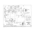
CD-C831W
� Playback can only be performed when a disc is loaded.
Is the Focus servo active? (Can you hear it working?) Yes Yes Does the DRF signal change from "L" to "H"? Yes Yes Is HF waveform normal (see the Fig.37-1, 2)? Yes Check the tracking system. Waveform is unstable.
0.5s 1.00 V IC1 16 FD 0.5s 10.0 V IC2 13 CLV+ 0.5s 10.0 V IC1 54 DRF 0.5s 2.00 V IC1 7 TE 2 1 3 4
No
Check the laser diode driver. Check the area around IC1(16) - (21) (focus servo circuit).
No
If the disc is not turning, the DRF should not change to "H".
Check the spin system.
No
Level is abnormal. Yes
Check the periphery of IC1 pins 41 and 42.
Check the spin system.
Waveform in case of normal play-back
HF 1.0V/DIV 0.5µsec/DIV(DC) IC1 41 (When playing back the disc)
Figure 37-1 � Check the tracking system.
Figure 37-2
Check waveform of IC1 pin 7 (TE). The waveform shown in Fig. 37-3 appears, and nodisc state appears soon. Tracking servo is inoperative. Yes Check the periphery of IC 1 pin 8 to pin 15, and IC 3 to CNP2.
Yes
Play is possible in TEST mode.
Yes
The unit will be initialized in Normal mode,but it will not Yes playback.
Normal jump is impeded, and the program top Yes cannot be reached.
Check the periphery of IC 1 pin 14.
Data cannot be read.
Yes
Check the VCO-PLL system.
5ms 1.00 V IC1 7 TE
4
5 ms 5.0 V IC1 54 DRF
3
Figure 37-3 � 37 �
|
|
|
> |
|