|
|
|
Categories
|
|
Information
|
|
Featured Product
|
|
|
 |
|
|
There are currently no product reviews.
 ;
Thank you very much for the manual. It is what I needed and it will be very helpful to me. The delivery of the manual was easy and very fast. I strongly recommend this site to other users. Best regards.
 ;
Excellent!! Got what I need and very fast!! Thank You
;
Manual acquired with good resolution, complete in all its pages, very good policy of the folder where are saved all products purchased.
;
Service manual very complete and clear. It was very helpfull for my work.
;
This is the 2nd time I download manuals from this website and I can say it's what I was expecting. It contains schematic, layout (decent quality), short description, parts and dissasembly instructions. I recomend it for anyone who wants to repair/modify this device.
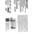
CD-DVD500H
The [No Disc] indication. (In case focus servo does not function.) Is the focus control signal output to the pin 14 of IC3701 ? Yes Is the focus control signal from the pin 158 of IC3701 input into the pin 23 of IC3801 ? Yes No Check the IC3701 DAC power source periphery circuit. If it is normal, replace IC3701. Check the focus control signal (FOD) line between the IC3801 and IC3701. Check M_5 V line. Is the focus control drive voltage output from the pins 17 and 18 of IC3801 ? Yes No No Is 8V voltage applied to the pins 8 of IC3801 ? Yes Replace IC3801. No Check the line between the IC3701 and the focus actuator terminal.
No
Focus control drive voltage applied to 47, 49 pin of CS3301 (focus actuator terminal) ? Yes Check the connection of optical pickup cable. If it is normal, replace the optical pickup mechanism Unit.
The DVD disc is not recognized. (When the laser beam does not go on) Is the drive signal (FLGA) of Q3301 (HF- MOD SW) No being output to the pin 37 of IC3701? Is the drive signal (LDO2) of Q3302 (LD POWER No CTL) being output to the pin 4 of IC3301 ? Yes No Is the voltage of 3.3 V being applied to the emitter of Q3301? And, is the voltage of 3.4 V being applied to the emitter of Q3302 ? Yes No Is the voltage of 3.1V and 2.3V being applied to the pins 34 and 43 of CS3301, respectively ? Yes Check the connection of optical pickup cable. If it is normal, replace the optical pickup mechanism Unit. Check the line from the pin 37 of IC3701, to the base of Q3301. Check the line between the pin 45 of IC3301 and the base of Q3302. Check the D_3.1 V line and A_5 V line.
Check the Q3301 and line between Q3302 and CS3301.
The CD disc is not recognized. (When the laser beam does not go on) Is the voltage of 3.4V being applied to the emitter of Q3303 ? Yes Is the voltage of 2.3V being applied to the pin 29 of CS3301 ? Yes Check the connection of optical pickup cable. If it is normal, replace the optical pickup mechanism Unit. No Check the A_5 V line.
No
Check the line between Q3303 and CS3301.
� 69 �
|
|
|
> |
|