|
|
|
Categories
|
|
Information
|
|
Featured Product
|
|
|
 |
|
|
There are currently no product reviews.
 ;
This is the original manufacturers service manual, with detailed info on the circit boards, explosion drawings of all parts in assembly order, and tuning instructions. The only thing missing is the information on the dimensions of the various drive belts. mail me if you need them. gcrossman_at_aol.com
;
Ordered service manuel for a hard to find plasma tv - your company made it easy to find and purchase - I will use you again
Thanks for your help
 ;
This is a high quality manual with clear schematic and components layout diagrams ; with service procedure included.
;
This service manual for the Kenwood KT-990D was reproduced really well ,is very legible and manual is complete.Combined with the low price paid,in the future,I will be checking Owner-Manuals.com any time I need a manual.
;
When I purchased this manual I had my doubts regarding the quality as the price was so reasonable as compared to other outlets.
The manual itself is of high standard the print is very clear as are the diagrams. Obviously with the diagrams one has to zoom in otherwise it is to small to be able to read.
Overall I am very pleased with the company who delivered as they said and with the manual they supplied.
I occasionally require a manual and now having registered with this company I shall order from them in the future.
CD-ES111H
NOTES ON SCHEMATIC DIAGRAM
� Resistor: To differentiate the units of resistors, such symbol as K and M are used: the symbol K means 1000 ohm and the symbol M means 1000 kohm and the resistor without any symbol is ohm-type resistor. Besides, the one with �Fusible� is a fuse type. � Capacitor: To indicate the unit of capacitor, a symbol P is used: this symbol P means pico-farad and the unit of the capacitor without such a symbol is microfarad. As to electrolytic capacitor, the expression �capacitance/withstand voltage� is used. (CH), (TH), (RH), (UJ): Temperature compensation (ML): Mylar type (P.P.): Polypropylene type � Schematic diagram and Wiring Side of P.W.Board for this model are subject to change for improvement without prior notice.
REF. NO SW1 SW401 SW402 SW403 SW404 SW701 SW702 SW703 SW704 SW705 SW706 SW707 SW708 SW709 SW710 DESCRIPTION PICKUP IN DISC UP/DOWN OPEN/CLOSE DISC NO. DISC 1 X-BASS/DEMO ON/STAND-BY OPEN/CLOSE DISK SKIP VIDEO/AUX TAPE PRESET DOWN PLAY/REPEAT PRESET UP STOP POSITION ON�OFF ON�OFF ON�OFF ON�OFF ON�OFF ON�OFF ON�OFF ON�OFF ON�OFF ON�OFF ON�OFF ON�OFF ON�OFF ON�OFF ON�OFF
� The indicated voltage in each section is the one measured by Digital Multimeter between such a section and the chassis with no signal given. 1. In the tuner section, indicates AM indicates FM stereo 2. In the main section, a tape is being played back. 3. In the deck section, a tape is being played back. 4. In the power section, a tape is being played back. 5. In the CD section, the CD is stopped. � Parts marked with � 1 � ( ) are important for maintaining the safety of the set. Be sure to replace these parts with specified ones for maintaining the safety and performance of the set.
REF. NO SW711 SW712 SW713 SW714 SW715 SW719 SW720 SW721 SW722 SW723 SW724 SW801 SW802 SW803
DESCRIPTION MEMORY/SET TUNING/TIME DOWN TUNING/TIME UP TIMER/SLEEP CLOCK EQUALISER VOLUME UP VOLUME DOWN TUNER(BAND) CD REC/PAUSE TAPE2 INITIALIZE TAPE1 INITIALIZE TAPE2 REC
POSITION ON�OFF ON�OFF ON�OFF ON�OFF ON�OFF ON�OFF ON�OFF ON�OFF ON�OFF ON�OFF ON�OFF ON�OFF ON�OFF ON�OFF
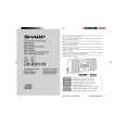
TYPES OF TRANSISTOR AND LED
FRONT VIEW
EC B (S) (G) (D) (1) (2) (3) 2SB562 C KRA102 M KRA107 M KRC102 M KRC104 M KRC107 M KTA1266 GR KSA1271 Y KTC3199 GR 2SC535- C 2SC2001 K KTC3203 Y
1
2 SVC348S KDV147B
3
� 16 �
|
|
|
> |
|