|
|
|
Categories
|
|
Information
|
|
Featured Product
|
|
|
 |
|
|
There are currently no product reviews.
 ;
Nice manual. Clear copy and very rare, to boot. Great price, too!
 ;
Excellent service manual. Complete service info. with schematics, step-by-step instructions and illustrations. Well worth the price!
;
Great product, helped me to restore vintage walkman cassette.
Just some pictures could be little bit more sharp and contrast
Thank you
;
I love older radio's and the service manuals that are sometimes hard to find. Was able to find a manual quite easily on this site.
;
Thank you for your shop manual! Your help was very useful - the device is repaired! Once again - Thank you! I wish you a successful business! Edward (Russia).
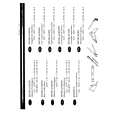
CD-ES222H/ES222E
REMOVING AND REINSTALLING THE MAIN PARTS
TAPE MECHANISM SECTION
Perform steps 1 to 6 and 8 of the disassembly method to remove the tape mechanism. (A1)x1 ø2x7mm (A1)x1 ø2x3mm
TAPE 1
How to remove the record/playback and erase heads (TAPE 1) (See Fig. 8-1)
1. When you remove the screws (A1) x 2 pcs., the record/ playback head can be removed.
How to remove the playback head (TAPE 2) (See Fig. 8-2)
1. When you remove the screws (B1) x 2 pcs., the erase head can be removed. 2. When you remove the screws (B2) x 2 pcs., the record/ playback head can be removed. Note: After replacing the heads and performing the azimuth adjustment, be sure to apply screwlock. Record/ Playback Head Figure 8-1 (B2)x1 ø2x7mm (B1)x2 ø2x8mm (B2)x1 ø2x3mm
TAPE 2
How to remove the pinch roller (TAPE 1,2) (See Fig. 8-3)
1. When you remove the screw (C1) x 1 pc., the pinch roller can be removed. Note: When installing the pinch roller, pay attention to the spring mounting position.
Erase Head Record/ Playback Head Figure 8-2
TAPE 1 TAPE 2
How to remove the motor (See Fig. 8-4)
1. Remove the belt. 2. Remove the screws (D1) x 4 pcs., to remove the motor bracket. 3. Remove the screws (D2) x 3 pcs., to remove the motor.
How to remove the belt (TAPE 1) (See Fig. 8-5)
1. Remove the main belt (F1) x 1 pc., from the motor side.
<A>
How to remove the belt (TAPE 2) (See Fig. 8-5)
1. Remove the main belt (G1) x 1 pc., from the motor side. 2. Remove the FF/REW belt (G2) x 1 pc.
Pinch Roller (C1)x1
Figure 8-3
Pinch Roller Pawl
Motor
(D1)x2 ø2x4mm
Motor TAPE 2 Main Belt (G1)x1 REW/FF Clutch Ass'y Motor
Motor Bracket
TAPE 2
Main Belt (G1)x1
TAPE 1 Main Belt (F1)x1
(D1)x2 ø2x4mm
Motor Bracket (D2)x3 Special Screw
TAPE 1
REW/FF Belt (G2)x1
Main Belt (F1)x1
Motor
Figure 8-5 �8�
Figure 8-4
|
|
|
> |
|