|
|
|
Categories
|
|
Information
|
|
Featured Product
|
|
|
 |
|
|
There are currently no product reviews.
 ;
Probably it never existed a 1081 official service manual from Commodore, it's look more like a NAPCEC service manual & diagrams compilation of the 1084 series and his variants, like the nap6523, 8cm505, 1084S, 1084P and obviously the 1081. It's more complete than other scans and the quality of the scans also are far superior. It has two circuit diagrams variants of the 1081, mono and stereo versions. It doesn't include a diagram for the Philips CM8500 or CM8501, they look like the 1081 but they are slightly different.
 ;
Rapid, clear well done as all the scheme I downloaded from this site. Great job very functional and very useful
;
Great copy of the manual, has all information required for servicing,
;
I work at an authorized service center and I can tell if a manual is as it should be. This one is. It may be a scan, but a very good one at that. The interesting part for me was the curcuit diagram which was scanned at high quality, making it as good as the original. I will definitely be back as a customer. I need not say this, but I will: the price was the best. Thank you owner-manuals.com .
;
really a very good manual even sometimes the quality is no so good as before still very readible and very very useful!
1
2
3
4
A
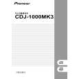
Notes on Replacement
Notes on replacing the Sheet SW
8 9
Mount the gear plate. Secure the gear plate, using the four screws. Gear plate
Place to adhere the Sheet SW
Notes: 1. Be careful not to warp the sheet SW. 2. Remove any dirt on the JOG holder to which the sheet SW is to be adhered. If some adhesive for the old sheet SW remains on the JOG holder, completely remove it with a cloth moistened with alcohol. 3. Do NOT place the sheet SW so that it is mounted on the rib of JOG holder 1000. 4. When adhering the sheet SW, be careful not to trap air bubbles in it. If air bubbles are formed, remove the sheet SW and adhere a new sheet SW. Do NOT reuse the removed sheet SW. 5. When making a connection, be sure to first release the lock of the connector then securely relock the connector after making the connection.
9 9 8
9
B
9
C
10 Remove the forced eject pin.
Forced eject pin
10
Sheet SW
D
11 Mount the cam plate. 12 Install the gear spring 200. 13 Mount the adjust plate. 14 Secure the adjust plate, using one screw.
Gear spring 200 JOG holder 1000 Rib
Place to adhere the SW cushions HH48/2
12 11
Adhere the cushions to the right and left of the engraved arrows (�) (12 positions in total) on the sheet SW.
E
Cam plate
14
Default value "0"
0
13
To increase the load
To decrease the load
+1 +2
-1 -2
SW cushion HH48/2
Engraved arrow
SW cushion HH48/2
-3
F
Note: For details on adjustment, see "Load Check mode for the JOG Dial."
Sheet SW Adjust plate
98
1 2
CDJ-1000MK3
3 4
|
|
|
> |
|