|
|
|
Categories
|
|
Information
|
|
Featured Product
|
|
|
 |
|
|
There are currently no product reviews.
 ;
It's a full manual. All the parts are in there. I haven't found the problem yett, but I am working on it; hope I can rebuild the part myself. To make it more secure and unbreakable this time. Because the part has failed several times before and costs a lot to let it be repaired.
Thanks so much for this rich illustrated and parted manual.
;
I downloaded the document. The manual was complete, well scanned and everything was legible. I could zoom in see what I needed to know. There's not much more that you can ask.
;
It was complete service manual with all needed service informations. Thanks.
 ;
El manual esta muy detallado, los numeros de partes y los esquemas de despiece son correctísimos y muy claros, tanto para los técnicos experimentados como para los novatos.
;
Ottima qualità grafica e completo nelle notizie. Costo abbastanza contenuto.
SCHEMATIC DIAGRAM
1 2
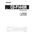
CD-P1450
Power Circuit
3 4 5
LIVE POWERCORD EC202 EC-TERMINAL
SW201 SW-POWER
0V
T201 4L50006430
13 12
J202 W501 CONNECTOR 5P ASSY
1
CN201
A
NEUTRAL
3
C201 EC201 EC-TERMINAL 0.01uF CN202
120V 230V
11
J201
4 5
9 7
1 2 3 4 5
1 2 3 4 5
TO PCB MAIN CN105
SW201 SW-POWER LIVE POWERCORD EC202 EC-TERMINAL
230V
T201
F201
1 3
13 12 11 9
T630mA/250V F202 T630mA/250V CN201 1 CONNECTOR 5P ASSY
B
NEUTRAL
C201 0.01uF
1 2 3 4 5
0V
5 7
4L50005840
EC201 EC-TERMINAL
2 3 4 5
TO PCB MAIN CN105
C
INSTRUCTIONS FOR SERVICE PERSONNEL BEFORE RETURNING APPLIANCE TO THE CUSTOMER, MAKE LEAKAGECURRENT OR RESISTANCE MEASUREMENTS TO DETERMINE THAT EXPOSED PARTS ARE ACCEPTABLY INSULATED FROM THE SUPPLY CIRCUIT.
1. Resistor values are in ohms (k=kilo-ohms, M=megohms). 2. Capacitor values are in microfarads (p=picofarads). 3. £Parts marked with this sign are safety critical components. They must always be replaced with identical components-refer to the appropriate parts list and ensure exact replacement.
NOTES:
CD-P1450
COMPACT DISC PLAYER
1 st Issue; November 2001
|
|
|
> |
|