|
|
|
Categories
|
|
Information
|
|
Featured Product
|
|
|
 |
|
|
There are currently no product reviews.
 ;
We received the manual in a timely manner and it was exactly what we were expecting. Excellent replacement for original Service Manual.
All schematics are very legible. We are really satisfied.
;
We received the manual in a timely manner and it was exactly what we were expecting. Excellent replacement for original Service Manual.
All schematics are very legible. We are really satisfied.
;
We received the manual in a timely manner and it was exactly what we were expecting. Excellent replacement for original Service Manual.
All schematics are very legible. We are really satisfied.
;
We received the manual in a timely manner and it was exactly what we were expecting. Excellent replacement for original Service Manual.
All schematics are very legible. We are really satisfied.
;
We received the manual in a timely manner and it was exactly what we were expecting. Excellent replacement for original Service Manual.
All schematics are very legible. We are really satisfied.
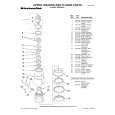
SECTION 3 ELECTRICAL BLOCK CHECKING
Note : 1. CD Block is basically designed to operate without adjustment. Therefore, check each item in order given. 2. Use YEDS-18 disc (3-702-101-01) unless otherwise indicated. 3. Use an oscilloscope with more than 10M� impedance. 4. Clean the object lens using an applicator with neutral detergent when the signal level is low than specified value with the following checks. Note : A clear RF signal waveform means that the shape � � � can be clearly distinguished at the center of the waveform. RF signal waveform
VOLT/DIV : 200mV TIME/DIV : 500ns
S Curve Check
oscilloscope BD board TP (FE) TP (VC)
level : 1.25 ± 0.25 Vp-p
E-F Balance Check
oscilloscope BD board
Procedure : 1. Connect oscilloscope to test point TP (FE) on BD board. 2. Connect between test point TP (FEI) and TP (VC) by lead wire. 3. Turn Power switch on. 4. Put disc (YEDS-18) in and turn Power switch on again and actuate the focus search. (Actuate the focus search when disc table is moving in and out.) 5. Check if the oscilloscope waveform (S-curve) is symmetrical between A and B. And confirm peak to peak level within 3±1 Vp-p. S-curve waveform
symmetry
TP (TE) TP (VC)
Procedure : 1. Connect test point TP1 (ADJ) to ground with a lead wire. 2. Connect oscilloscope to test point TP (TE) on BD board. 3. Turned Power switch on. 4. Put disc (YEDS-18) in to play the number five track. 5. Press the �3� button. (The tracking servo and the sledding servo are turned OFF.) 6. Check the level B of the oscilloscope's waveform and the A (DC voltage) of the center of the Traverse waveform. Confirm the following : A/B � 100 = less than ± 22% Traverse waveform
A within 3 ± 1 Vp-p B
Center of the waveform B
6. After check, remove the lead wire connected in step 2. 0V Note : � Try to measure several times to make sure than the ratio of A : B or B : A is more than 10 : 7. � Take sweep time as long as possible and light up the brightness to obtain best waveform. 7.
A (DC voltage)
level : 1.3 ± 0.6 Vp-p
RF Level Check
oscilloscope BD board TP (RF) TP (VC)
Press the �8� button. (The tracking servo and sledding servo are turned ON.) Confirm the C (DC voltage) is almost equal to the A (DC voltage) is step 6. Traverse waveform
Procedure : 1. 2. 3. 4. Connect oscilloscope to test point TP (RF) on BD board. Turned Power switch on. Put disc (YEDS-18) in to play the number five track. Confirm that oscilloscope waveform is clear and check if RF signal level is correct or not.
0V
C (DC voltage)
Tracking servo Sledding servo OFF
Tracking servo Sledding servo ON
8.
Disconnect the lead wire of TP (ADJ) connected in step 1.
�8�
|
|
|
> |
|