|
|
|
Categories
|
|
Information
|
|
Featured Product
|
|
|
 |
|
|
There are currently no product reviews.
 ;
Finding the owners manual for my Pioneer CRWM62R is greatly appreciated. I had searched several other web sites with no success. Although my manual was not listed on your site for immediate download, I recevied an email within a few hours that my ower's manual was posted for me. I had no difficulty downloading the manual for my 20 year old multi-cassette player. Owner Manuals provides a service that is valuable, easy-to-use, accurate , efficient, and priced fairly. I thank you.
;
Excellent manual - just what I needed. Although currently available only in German, their are lots of pictures which makes it all very clear.
;
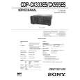
PHILIPS PE1642 Owner's Manual
Hi,
you have complet fullfilled my expectance.
Price is OK.
Robert Schmid
 ;
Came in the mail within a few hours. Gave clear instruktion on maintaines. Is of great use to have this manual in house
;
Easy to access. Clear instructions. No problems. Printed fine.
6-2. ELECTRICAL ADJUSTMENT
Note: 1. CD Block is basically designed to operate without adjustment. Therefore, check each item in order given. 2. Use YEDS-18 disc (3-702-101-01) unless otherwise indicated. 3. Use an oscilloscope with more than 10M� impedance. 4. Clean the object lens by an applicator with neutral detergent when the signal level is low than specified value with the following checks. S-Curve Check
oscilloscope BD board TP (FE1) TP (VC)
Note: A clear RF signal waveform means that the shape ��� can be clearly distinguished at the center of the waveform.
RF signal waveform
VOLT/DIV : 200mV TIME/DIV : 500ns level : 1.2
+0.25 �0.20
Vp-p
Adjustment Location: BD board E-F Balance Check
oscilloscope BD board TP (TE) TP (VC)
Procedure : 1. Chuck the disc (YEDS-18) beforehand, and disconnect the power cord from the outlet. 2. Connect oscilloscope to test point TP (FE1) on BD board. 3. Connect test point TP1 (ADJ) on MAIN board to ground with lead wire. 4. The ADJ mode is set when the power cord is inserted into the outlet and power is supplied. 5. The fifth track is played automatically. 6. Press the CHECK button. 7. Check the oscilloscope waveform (S-curve) is symmetrical between A and B. And confirm peak to peak level within 3±1 Vp-p.
S-curve waveform
symmetry
Procedure : 1. Chuck the disc (YEDS-18) beforehand, and disconnect the power cord from the outlet. 2. Connect oscilloscpe to test point TP (TE) on BD board. 3. Connect test point TP1 (ADJ) on MAIN board to ground with lead wire. 4. The ADJ mode is set when the power cord is inserted into the outlet and power is supplied. 5. The fifth track is played automatically. 6. Press the GROUP 3 button. (The tracking servo and the sledding servo are turned OFF.) 7. Check the level B of the oscilliscope's waveform and the A (DC voltage) of the center of the Traverse waveform. Confirm the following : A/B x 100 = less than ± 22%
A Within 3 ± 1 Vp-p B
Traverse waveform
Center of the waveform B
8. Pressing the 1/u button stops the output of the waveform (s curve). 9. After check, remove the lead wire connected in step 3. Note : � Try to measure several times to make sure than the ratio of A : B or B : A is more than 10 : 7. � Take sweep time as long as possible and light up the brightness to obtain best waveform. Adjustment Location: BD board
0V
A (DC voltage)
level : 1.3 ± 0.6 mVp-p
8. Press the GROUP 8 button. (The tracking servo and sledding servo are turned ON.) Confirm the C (DC voltage) is almost equal to the A (DC voltage) is step 7.
Traverse waveform
RF Level Check
oscilloscope BD board TP (RF) TP (VC)
0V
C (DC voltage)
Procedure : 1. Connect oscilloscope to test point TP (RF) on BD board. 2. Turn Power switch on. 3. Put disc (YEDS-18) in to play the number five track. 4. Confirm that oscilloscope waveform is clear and check RF signal level is correct or not.
Tracking servo Sledding servo OFF
Tracking servo Sledding servo ON
9. Disconnect the lead wire of TP1 (ADJ) connected in step 2. Adjustment Location: MAIN board
� 17 �
|
|
|
> |
|