|
|
|
Categories
|
|
Information
|
|
Featured Product
|
|
|
 |
|
|
There are currently no product reviews.
 ;
Complete service manual in very good scanning quality with all schematic and PWB graphics as well as assembly & maintenance instructions. A slight drawback is that the rastering of the PWB graphics sometimes makes it a bit difficult to follow fine traces, but no showstopper.
;
Purchased the manual that I was looking for at a great price and could download it easily.. Great service experience and for future purchases I plan to use the site. Thank you very much
 ;
Service manual in good quality, it was very helpful to me. Perfect service, I am very satisfied.
Jochen Kelm
;
Exellent manual ,it was in great condition,and got all the info i expected,5 stars!!
;
I searched the Internet exhaustively for this manual and Owner-Manuals was the least expensive...but provided an excellent reproduction within 4 hours. Very satisified.
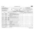
Disc Sensor Adjustment Be sure to perform this adjustment after sensor adjustment in MECHANICAL ADJUSTMENT. Connection:
MAIN board CN506 D.S GND T.P D.S: Pin 1 T.P: Pin 3 GND: Pin 2 oscilloscope
5. Rotate the DISC/CHARACTER knob in the counterclockwise direction and the disc table starts to rotate in the same direction. Check that the waveform at this time is the same as that in step 4. If larger by a considerable extent, rotate the DISC/CHARACTER knob in the clockwise direction and the disc table starts to rotate in the same direction. Repeat from step 4. 6. Rotate RV501 of the MAIN board and adjust so that the H and L portions of the D.S waveform become the same.
Waveform:
D.S
D.S
Adjust so that these widths become the same.
Adjustment Location: MAIN board
P.T
1. Connect the oscilloscope to Pins 1, 2, and 3 of CN506 of the MAIN board. 2. Check that no discs are loaded in the unit. 3. With the power ON, while pressing the GROUP 5 and § OPEN/CLOSE buttons, press the +100 button. The disc table starts to rotate in the clockwise direction. 4. Loosen the fixing screw, move the mounting board (SENSOR), and secure the mounting board (SENSOR) at the point the H portion of the P.T waveform comes the center of the H portion of the D.S waveform.
Fixing screw Mounting board (SENSOR)
D.S
P.T
Should be at the center
� 18 �
|
|
|
> |
|