|
|
|
Categories
|
|
Information
|
|
Featured Product
|
|
|
 |
|
|
There are currently no product reviews.
 ;
Wonderful service... doubt that I could have made the repairs to my turntable without this service manual. Great help!
Well worth the price paid!
;
nice completed SERVICE MANUAL as the description THANK YOU !!!-
;
The service manual is as described and received the link to the download sooner than expected. Great service, quality product. This site is a big help in the electronics repair business.
;
Il service manual molto accurato. Rapidi nella risposta
;
Quick site processing. A complete and very useful manual with all details. Thank you!
SECTION 1 SERVICING NOTES
1-1. WRITING FOCUS/TRACKING AUTO GAIN DATA
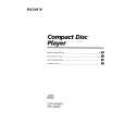
In general for the CD players that use a digital servo IC, the focus/ tracking gain is automatically adjusted each time a disc is changed. In this set, the gain in test disc (YEDS-18) has been written to a nonvolatile memory (IC803: X24C01S) on the Display Board, and therefore the gain is not readjusted even if a disc is changed. Accordingly, always write auto gain data when replacing the Servo Board, IC803 on Display Board, or optical pick-up. 1)Connect CN805 1 pin (IN/OUT SW) and 6 pin (GND) on Display Board. Under this condition, the set will operate even when the disc lid is open (or Key Board is not connected). 2)Connect TP (ADJ: CN105 3 pin) on Servo Board to GND, and TP (VC: CN108 2 Pin) to TP3 (TEI: IC105 @¶ pin) with lead wires respectively. 3)Connect an oscilloscope to TP (TE: CN108 1 pin).
Oscilloscope SERVO board TP (TE) TP (VC)
+ �
1-2. AF MODE
With the TP (AFJ: CN105 2 Pin) connected to the GND on Servo Board, turn on the POWER switch, and the AF mode is activated and the following checking can be made. 1-2-1. FL tube check All tubes turn on, then if · button is pressed, the display will be as shown below. (Segment ON 1)
(Segment ON 1)
IF P button is pressed, the display will be as shown below. (Segment ON 2)
2 6 12 16 18 8 14 20 4 10
(Segment ON 2)
4)Insert the test disc (YEDS-18), turn on POWER switch, and play fifth music with · (PLAY) and AMS Keys on the Remocon. 5)Adjust RV101 so that the waveform on oscilloscope is verticolly symmetric with respect to the A [Vdc], and also its level is 1.3 ± 0.6 Vp-p.
B 0Vdc A
If STOP p is pressed, all tubes turn on again.
symmetric level: 1.3 ± 0.6 Vp-p
At this time, A/B � 100 = ± 22 (%) or less 6)The auto gain data are written when a lead wire between TP (ADJ: CN105 3 pin) and GND is removed. Note: If the POWER switch was turned on without connecting TP (ADJ) to the GND, auto gain data are not written to the memory even if a disc is inserted, but the previous data saved in the memory are used as focus/tracking data.
�3�
|
|
|
> |
|