|
|
|
Categories
|
|
Information
|
|
Featured Product
|
|
|
 |
|
|
There are currently no product reviews.
 ;
I am satisfied with the service. And if need another manual, i will definitely buy from this site. Keep up the good work.
;
have download a number of manuals todate , most are excellant, one or two sometimes a little difficult to read but a least avaialable, great site .
Brad.
;
Excellent had everything I wanted, very happy with purchase
 ;
This service is relatively cheap, document is fast available, schematic is readable.
Thanks.
;
So far I´m a satisfied customer. I have only downloaded "TECHNICS SX-KN470 Service Manual" maybe I will use it later.
Best regards
Peter
CDX-4000RV
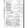
3-6. PRINTED WIRING BOARDS � CD MECHANISM SECTION �
THIS NOTE IS COMMON FOR PRINTED WIRING BOARDS AND SCHEMATIC DIAGRAMS. (In addition to this, the necessary note is printed in each block.) for schematic diagram: � All capacitors are in µF unless otherwise noted. pF: µµF 50 WV or less are not indicated except for electrolytics and tantalums. � All resistors are in � and 1/4 W or less unless otherwise specified. � % : indicates tolerance. � f : internal component. � C : panel designation. Note: The components identified by mark 0 or dotted line with mark 0 are critical for safety. Replace only with part number specified. � U : B+ Line. � Power voltage is dc 14.4V and fed with regulated dc power supply from ACC and BATT cords. � Voltages are taken with a VOM (Input impedance 10 M�). Voltage variations may be noted due to normal production tolerances. � Waveforms are taken with a oscilloscope. Voltage variations may be noted due to normal production tolerances. � Circled numbers refer to waveforms. � Signal path. F : FM f : MW J : CD for printed wiring boards: � X : parts extracted from the component side. � Y : parts extracted from the conductor side. � x : parts mounted on the conductor side. � a : Through hole. � b : Pattern from the side which enables seeing. (The other layer�s patterns are not indicated.) Caution: Pattern face side: (Side B) Parts face side: (Side A) Parts on the pattern face side seen from the pattern face are indicated. Parts on the parts face side seen from the parts face are indicated.
24
24
|
|
|
> |
|